Introduction
This article is the final installment of the FreeRTOS series. In this tutorial, we will learn how to use a Mutex (Mutual Exclusion) to allow multiple tasks to safely share a common resource.
A mutex is one of the most widely used synchronization mechanisms provided by FreeRTOS. It prevents data conflicts when multiple tasks attempt to access the same resource simultaneously, ensuring that shared resources remain consistent and are accessed safely.
In this tutorial, we will use a custom-designed dual-channel PT100 Analog Front End (AFE) to read two PT100 sensors from separate tasks. Both tasks will share the same UART2 peripheral to send the measured data to a PC. This hands-on experiment demonstrates how a mutex protects a shared resource in a real embedded system.
What is a Mutex?
A Mutex (Mutual Exclusion) is a synchronization mechanism that prevents multiple tasks from using the same shared resource simultaneously. As its name suggests, it provides mutual exclusion, allowing only one task to access a resource at a time while blocking all other tasks until the resource is released.
A mutex is one of the most commonly used synchronization mechanisms provided by FreeRTOS. It prevents data conflicts when multiple tasks attempt to access the same resource simultaneously, ensuring the consistency and integrity of shared resources.
For example, suppose two tasks share a single UART peripheral to transmit strings. If both tasks access the UART at the same time, the order of access to the shared resource is no longer guaranteed, making correct operation unpredictable.
When multiple tasks access the same shared resource simultaneously and produce unpredictable results, the situation is called a Race Condition.
The symptoms of a race condition vary depending on the system implementation and the behavior of the device driver. For example, strings transmitted by two tasks may become interleaved, some data may be lost, or data from one task may fail to be transmitted correctly.
In this experiment, we first ran two tasks that accessed UART2 simultaneously without using a mutex. Although the transmitted strings were not interleaved, we observed that data from the second task was not transmitted correctly. This is one example of a race condition caused by two tasks attempting to access the shared UART2 peripheral at the same time.
To solve this problem, we use a mutex. Before accessing a shared resource, a task takes (acquires) the mutex. After it has finished using the resource, it gives (releases) the mutex. Any other task must wait until the mutex becomes available again, ensuring that only one task can access the shared resource at any given time.
Unlike a semaphore, a mutex can only be released by the same task that acquired it. This ownership mechanism is one of the key features that makes a mutex more suitable for protecting shared resources.
The operation sequence is as follows:
- A task takes (acquires) the mutex.
- The task uses the shared resource (UART2).
- After the operation is complete, the task gives (releases) the mutex.
- Another waiting task acquires the mutex and performs the same operation.
By allowing only one task to access a shared resource at a time, a mutex prevents race conditions and improves the stability of the system.
The following link points to the official FreeRTOS documentation for mutexes.
The figure below is an animation provided on the FreeRTOS website that illustrates how a mutex works.
In the figure, you can see that Task A and Task B use the xSemaphoreTake() and xSemaphoreGive() APIs.
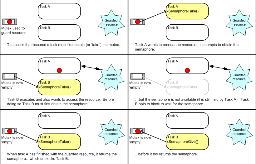
This is because FreeRTOS uses the same xSemaphoreTake() and xSemaphoreGive() APIs for mutexes. Although the API names include the word Semaphore, the object created is actually a Mutex, so it behaves according to mutex semantics.
In other words, only the task that acquires a mutex can release it, and mutexes also support the Priority Inheritance mechanism. These features make mutexes well suited for protecting shared resources safely when multiple tasks are running.
In this tutorial, we will use a custom-designed dual-channel PT100 Analog Front End (AFE) to read two PT100 sensors from separate tasks. Both tasks will share the same UART2 peripheral to transmit the measured values to a PC. We will then compare the system behavior before and after applying a mutex through real hardware experiments to demonstrate how a mutex protects shared resources safely.
Hardware Configuration
In this tutorial, we build a system in which two PT100 sensors are read independently by separate FreeRTOS tasks, while both tasks share a single UART2 peripheral to transmit the measured values to a PC. Through this experiment, we will demonstrate how a mutex protects the shared UART2 resource using real hardware.
The hardware is configured as shown in the diagram below.
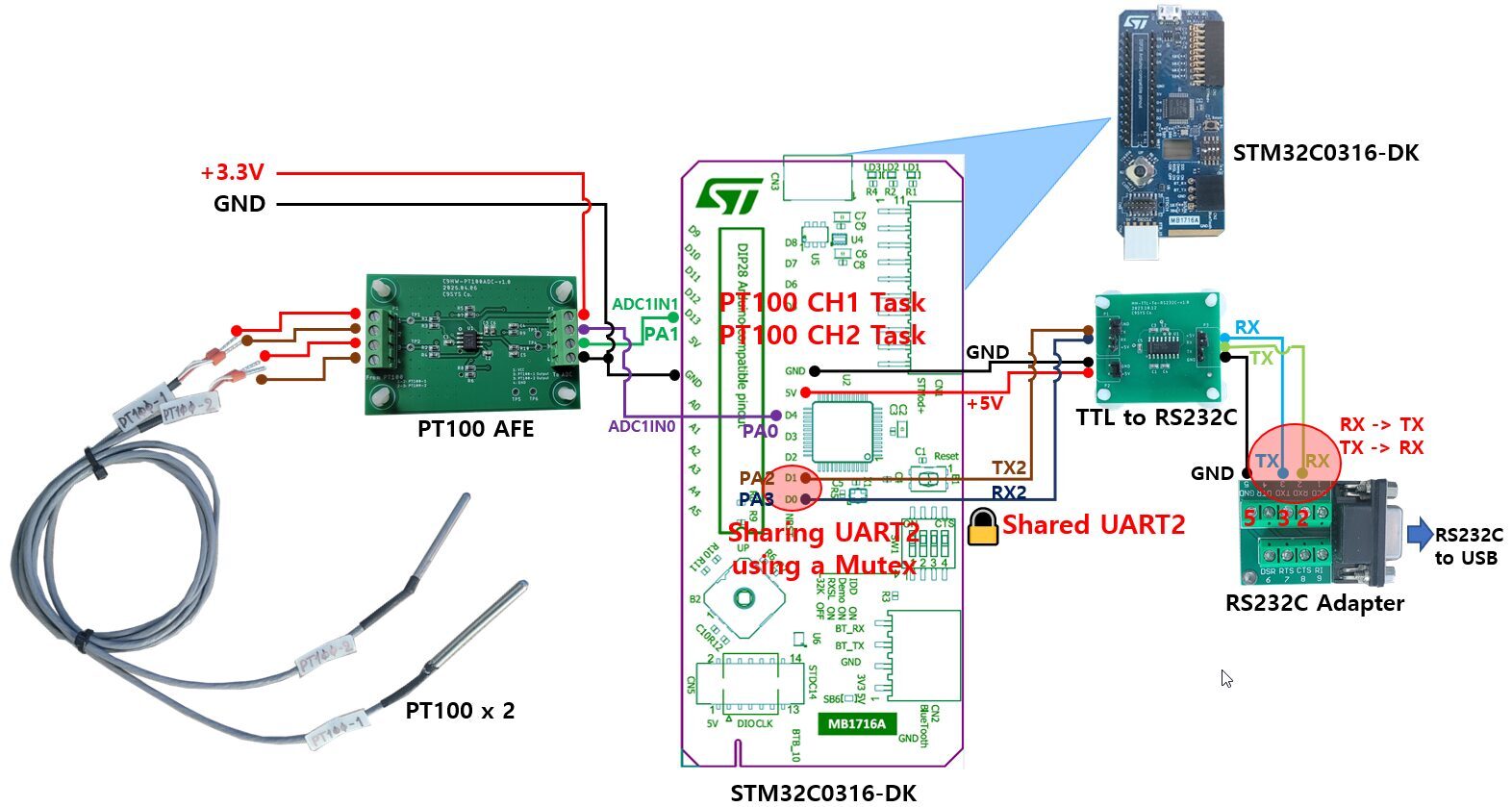
The function of each hardware component is as follows.
- PT100 ×2: Two temperature sensors. Each sensor is read by a separate FreeRTOS task.
- PT100 AFE (Analog Front End): Converts the resistance variation of the PT100 into an analog voltage that can be measured by the STM32 ADC.
- STM32C0316-DK: The main controller board running FreeRTOS. It executes the two PT100 tasks and manages the mutex.
- UART2: A shared communication resource used by both tasks. Access to UART2 is synchronized using a mutex so that only one task can use it at a time.
- TTL-to-RS232C Converter: Converts the UART TTL signals into RS-232 voltage levels.
- RS232C Extension Board: A breakout board that provides convenient access to the DB9 connector pins.
- USB-to-RS232C Cable: Converts the RS-232 signals to USB for communication with the PC.
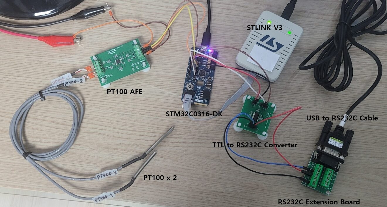
The photograph below shows the actual hardware setup used in this experiment.
Program Architecture
In this experiment, two PT100 sensors are read independently by separate FreeRTOS tasks. Each task measures the sensor value using the ADC and then transmits the measured data to a PC through the shared UART2 peripheral.
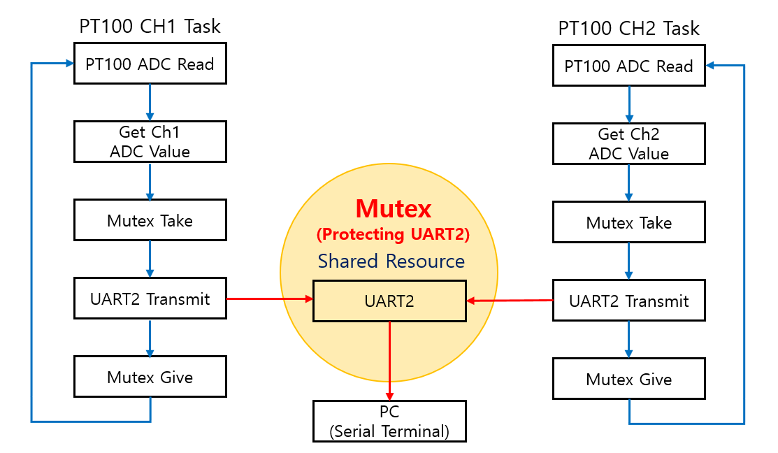
First, each task reads the output voltage from the PT100 AFE using the ADC and obtains the corresponding ADC value. Before accessing the shared UART2 peripheral, the task acquires the mutex (takes the mutex).
Only the task that has acquired the mutex is allowed to use UART2. Any other task attempting to access UART2 must wait until the mutex is released. After transmitting the ADC value to the PC through UART2, the task releases the mutex (gives the mutex), allowing another waiting task to access UART2.
In this way, the two tasks share a single UART2 peripheral sequentially, preventing race conditions and ensuring that ADC data is transmitted to the PC reliably.
The program execution sequence is as follows:
- Read the PT100 ADC value.
- Take (acquire) the mutex.
- Transmit the data to the PC through UART2.
- Give (release) the mutex.
- Another task repeats the same sequence.
By allowing only one task to access the shared resource at a time, the mutex prevents race conditions and improves the overall reliability and stability of the system.
Creating the Project and Writing the Firmware
Creating the Project and Verifying Basic Task Operation
For this tutorial, we created a new project named C9SW-FreeRTOS-M-Mutex by copying the previously developed C9SW-FreeRTOS-M-Queue project, which already contains a working FreeRTOS port.
The user source files used in this experiment, pt100_adc.c and pt100_adc.h, were then added to the MyApp folder.
These files implement the PT100 ADC reading and UART2 data transmission functions. Each PT100 channel is processed independently by its own FreeRTOS task.
In this tutorial, we did not create a separate UART2 driver module. Instead, we used the UART driver provided by the STM32 HAL library. This approach keeps the software simple and allows us to focus directly on demonstrating how a mutex protects a shared resource.
The figure below shows the completed project structure.
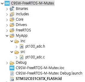
At this stage, only the basic project structure has been prepared. In the next step, we will create two FreeRTOS tasks and verify that the FreeRTOS scheduler is operating correctly.
First, we create the two tasks. Each task is created inside its initialization function using the xTaskCreate() API.
The code below shows the task initialization functions.
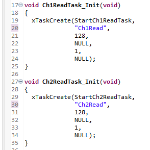
Ch1ReadTask_Init() and Ch2ReadTask_Init() each create a FreeRTOS task that executes StartCh1ReadTask() and StartCh2ReadTask(), respectively.
Both tasks are created with Priority 1 and a stack size of 128 words. In this experiment, the two tasks are assigned the same priority so that the FreeRTOS scheduler can schedule them fairly.
Next, we will implement the actual task functions, StartCh1ReadTask() and StartCh2ReadTask().
Before implementing the PT100 reading and mutex functionality, we will first write a simple test program to verify that the FreeRTOS scheduler is running correctly.
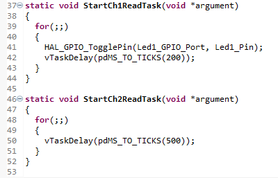
In StartCh1ReadTask(), LED1 is toggled every 200 ms so that we can verify that the task is running correctly.
In contrast, StartCh2ReadTask() does not implement its final functionality yet. Instead, it simply executes a 500 ms delay. In the next step, we will add the PT100 ADC reading and UART2 data transmission functions to this task.
To execute the task initialization code and start the tasks, we need to call the initialization functions in main.c and then start the FreeRTOS scheduler.
The code is shown below.
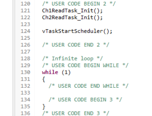
After running the program, we confirmed that LED1 toggled as expected. This verified that the FreeRTOS scheduler was operating correctly and that both tasks were successfully created and running without any issues.
PT100 ADC Reading
So far, we have verified that the FreeRTOS scheduler and the two tasks are operating correctly by using a simple LED toggle test.
Next, we will implement the actual PT100 sensor reading functionality. Each task periodically reads its assigned ADC channel and converts the output voltage from the PT100 AFE into an ADC value.
In this tutorial, PT100 Channel 1 uses ADC1_IN0 (PA0), while PT100 Channel 2 uses ADC1_IN1 (PA1). Each task is configured to read only its assigned ADC channel, allowing the two PT100 sensors to be measured independently.
For the ADC configuration, we used the default settings generated by STM32CubeMX, with only the sampling time modified. Since the output of the PT100 AFE is stable rather than high-speed, we increased the sampling time to improve conversion accuracy. Both Sampling Time Common 1 and Sampling Time Common 2 were changed from the default 1.5 cycles to 79.5 cycles, while all other ADC settings remained unchanged.
The figure below shows the updated ADC sampling time configuration.

Next, we will implement the function that reads the PT100 ADC values.
To use the ADC from another source file, the ADC handle (hadc1) generated by CubeMX must be declared as an extern variable. We also declare variables to store the ADC values for each channel.
The code is shown below.
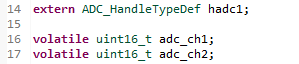
The variables adc_ch1 and adc_ch2 are declared as volatile so that their values can be monitored in real time using Live Expressions during debugging.
Next, we will implement the PT100_ReadADC() function, which performs the actual ADC conversion.
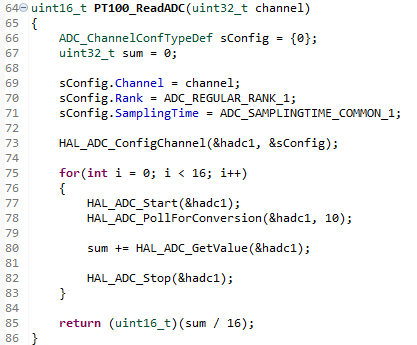
The PT100_ReadADC() function first selects the ADC channel specified by its input parameter and then performs 16 ADC conversions. The conversion results are averaged to reduce noise, and the final ADC value is returned.
The two tasks that call PT100_ReadADC() are shown below.
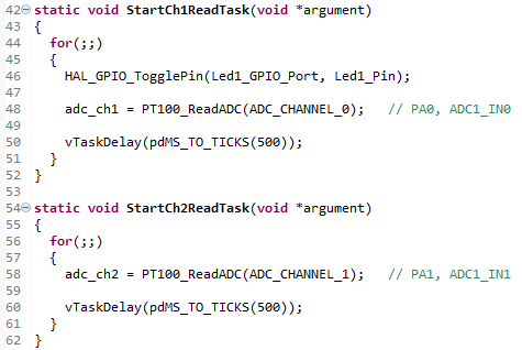
Both tasks are configured to run at 500 ms intervals. As a result, each task reads its assigned ADC channel once every 500 ms.
To monitor the ADC values in real time, add adc_ch1 and adc_ch2 to Live Expressions.
Build and download the project, then verify in Live Expressions that the ADC values for both channels are updated correctly.
The figure below shows the Live Expressions window.
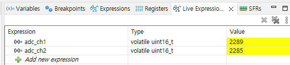
As shown, the ADC values for both channels are displayed correctly.
To verify that the ADC values respond to temperature changes, I warmed the PT100 Channel 1 sensor by holding it in my hand.
The figure below shows the updated Live Expressions values.
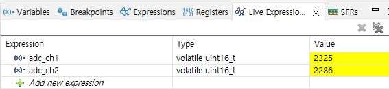
You can see that the value of adc_ch1 increased from 2289 to 2325, while adc_ch2 remained almost unchanged. This confirms that the two ADC channels operate independently and that each FreeRTOS task correctly reads only its assigned PT100 sensor.
As demonstrated above, we have verified that the ADC values from both PT100 channels can be read correctly. In the next step, we will implement the functionality to transmit the measured ADC values to a PC via UART2.
Transmitting ADC Values via UART
Now we will implement the code to transmit the measured ADC values to a PC through UART2.
First, declare the UART2 handle as an extern variable in pt100_adc.c so that it can be accessed from this source file.

Each task uses the snprintf() function to convert the ADC value into a text string and then transmits it through UART2 using the HAL_UART_Transmit() function.
The code for each task is shown below.
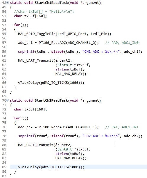
During the initial scheduler verification, the task delay was set to 500 ms. However, the output was updated too quickly to observe comfortably in the PC terminal. Therefore, for the UART transmission test, the delay for both tasks was increased to 1000 ms.
After running the program, we confirmed that the ADC values from both Channel 1 and Channel 2 were displayed in the Docklight terminal application on the PC.
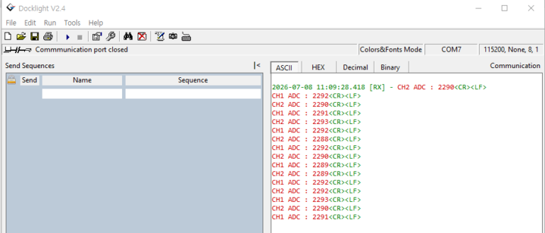
However, the output pattern revealed an interesting behavior.
Both tasks were configured to transmit data over UART every 1000 ms. However, the terminal displayed the outputs alternately—CH1, then CH2, then CH1 again. As a result, each individual channel was updated only once every 2 seconds.
In other words, although UART messages appeared on the terminal approximately once every 1 second, CH1 was transmitted every 2 seconds, and CH2 was also transmitted every 2 seconds.
This behavior occurred because the two tasks were sharing the same UART2 peripheral without any mechanism to coordinate access to the shared resource. As a result, the intended transmission interval for each task could not be maintained.
In the next step, we will apply a mutex to protect the UART2 communication section, allowing the two tasks to share the UART safely and maintain the intended transmission interval.
Applying the Mutex
Now we will modify the code to apply a mutex for protecting the shared UART2 resource.
The mutex can be implemented in the following four steps:
- Declare a global mutex handle.
- Create the mutex.
- Call the initialization function before starting the FreeRTOS scheduler.
- Protect the UART transmission section inside each task.
First, declare a mutex handle in pt100_adc.c to protect UART2.

Next, write an initialization function that creates the mutex using the xSemaphoreCreateMutex() API.
The code is shown below.
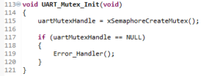
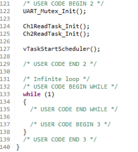
Since the mutex only needs to be created once before the scheduler starts, call UART_Mutex_Init() from main.c before calling vTaskStartScheduler().
The code is shown below.
Finally, protect the UART2 communication section in each task by using the xSemaphoreTake() and xSemaphoreGive() APIs.
The code is shown below.
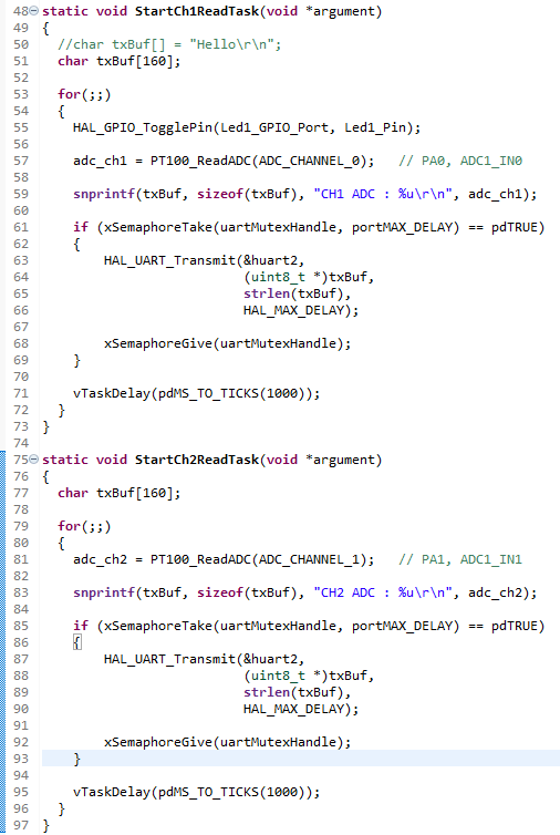
Before transmitting data through UART2, each task first attempts to acquire the mutex by calling xSemaphoreTake(). Since the timeout parameter is set to portMAX_DELAY, the task will wait indefinitely until the mutex becomes available.
Once the mutex has been successfully acquired, the task transmits the ADC value through UART2 using HAL_UART_Transmit().
After the transmission is complete, the task immediately releases the mutex by calling xSemaphoreGive(), allowing another waiting task to access the shared UART2 peripheral.
By enclosing only the UART transmission code with the mutex, the shared resource is protected while the ADC conversion and data formatting continue to execute independently in each task. This minimizes the time the mutex is held, allowing the two tasks to share UART2 efficiently while preventing race conditions.
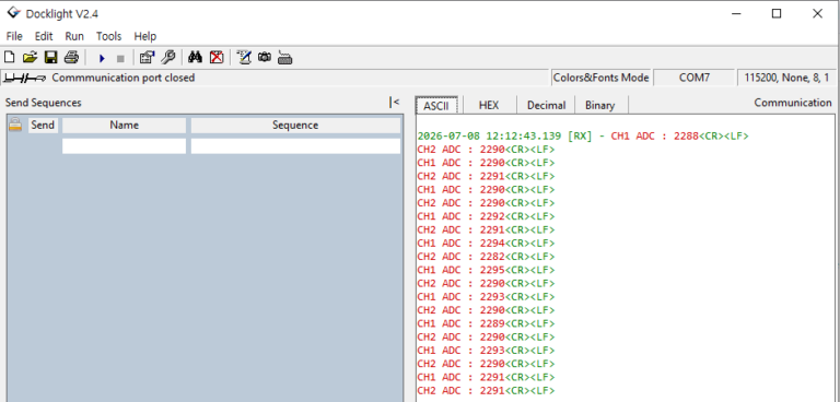
After applying the mutex, we confirmed that each task maintained its intended 1-second execution interval. As a result, the ADC values from both channels were transmitted almost simultaneously every second.
The figure below shows the UART output after the mutex was applied.
Test Results
After applying the mutex, we ran the program again and compared the results.
Before the mutex was applied, both tasks were configured to run every 1000 ms, yet CH1 and CH2 were transmitted alternately. As a result, each channel was updated only once every 2 seconds.
After protecting the UART2 transmission section with a mutex, however, both CH1 and CH2 maintained their intended 1-second transmission interval.
In Docklight, the ADC values from CH1 and CH2 were transmitted consecutively within the same one-second period, confirming that both tasks were sharing UART2 safely and reliably.
This experiment clearly demonstrates the difference in system behavior before and after applying a mutex.
Conclusion
In this tutorial, we learned how to use a FreeRTOS mutex (Mutual Exclusion) to allow two tasks to safely share a single UART2 peripheral.
Using two PT100 sensors, we created two independent FreeRTOS tasks and compared the system behavior before and after applying a mutex while both tasks shared the same UART2 peripheral. This real hardware experiment clearly demonstrated the role and importance of a mutex in controlling access to a shared resource.
With this article, we conclude the STM32C0316-DK FreeRTOS tutorial series.
Throughout this series, we explored the core features of FreeRTOS step by step using real hardware—from manually porting the FreeRTOS kernel to implementing Tasks, Queues, Binary Semaphores, and Mutexes.
I hope this series has helped beginners understand how FreeRTOS works internally and provided a practical foundation through hands-on experiments with real hardware.