Introduction
In the previous article, we ported Zephyr RTOS to an STM32-based custom board and covered the basic exercises, including LED control, and threads. Through these exercises, we became familiar with the Zephyr development environment, Devicetree, and the basic use of Zephyr APIs.
This time, we will move to the ESP32 CAN Board platform, port Zephyr to the board, and continue our hands-on exercises.
The ESP32 is a widely used MCU for IoT projects because it provides built-in Wi-Fi and Bluetooth connectivity at an affordable price. In particular, an ESP32 CAN Board with CAN functionality provides a useful platform for learning both industrial communication and IoT applications.
However, this board is not officially supported by Zephyr as-is, so board-specific porting is required. In this article, we will create the necessary board definition for the ESP32 CAN Board and control its RGB LED to verify that Zephyr is running correctly.
In the following articles, we will use the board ported here to explore various ESP32 features, including GPIO, UART, CAN, and Wi-Fi, one by one using Zephyr APIs.
ESP32 CAN Board Overview
The board used in this exercise is the ESP32 CAN-BUS Board from SK Pang Electronics. It integrates an ESP32-WROOM-32 module and a CAN transceiver on a single board, supporting both firmware downloading via USB-C and CAN communication.
With built-in Wi-Fi and Bluetooth, the board is well suited for developing IoT applications. Its CAN interface also makes it useful for hands-on experiments with industrial communication.
Throughout this series, we will use this board to explore various ESP32 features, including GPIO, UART, CAN, and Wi-Fi, step by step using Zephyr RTOS.
The ESP32 CAN Board used in this exercise is shown below.
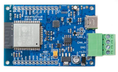
The main features of the ESP32 CAN Board are as follows:
- ESP32-WROOM-32 (Dual-Core Tensilica LX6, up to 240 MHz)
- Wi-Fi (802.11 b/g/n)
- Bluetooth Classic and BLE
- 520 KB SRAM
- 4 MB Flash
- Built-in CAN Transceiver
- USB Type-C Programming Support
- Built-in RGB LED
- External power input with reverse-polarity protection
Detailed specifications of the board are available at the link below. The schematic and demo code can also be downloaded from the same page.
Now that we have reviewed the main features of the ESP32 CAN Board, the next step is to port the board to Zephyr so that it can be used with Zephyr RTOS.
Board Porting
In the previous STM32 Zephyr porting exercise, we created a custom board by manually writing each of the required board files. However, the ESP32 CAN Board used in this exercise is based on the ESP32-WROOM-32 module. Therefore, instead of creating everything from scratch, we will create a new board by modifying only the necessary parts of the officially supported esp32_devkitc board definition.
In other words, rather than creating all the board files from the beginning, we will refer to the board definition of esp32_devkitc and modify it to match the ESP32 CAN Board. This approach allows us to reuse configurations that have already been verified in Zephyr, making the porting process easier and more reliable.
The reference board used in this exercise is esp32_devkitc.
Zephyr officially supports a wide variety of development boards. When a board has a hardware configuration similar to an existing supported board, using that board as a reference and adapting it to the new hardware is a common approach to board porting.
Checking the esp32_devkitc Board and Creating a New Board Directory
First, let’s locate the esp32_devkitc board that is officially supported by Zephyr.
The board files are located in the following directory:
zephyr
└── boards
    └── espressif
        └── esp32_devkitc
This directory contains the files required to define the board, including the DTS (Devicetree), Kconfig, and CMake configuration files.
The directory structure of the esp32_devkitc board is shown below.
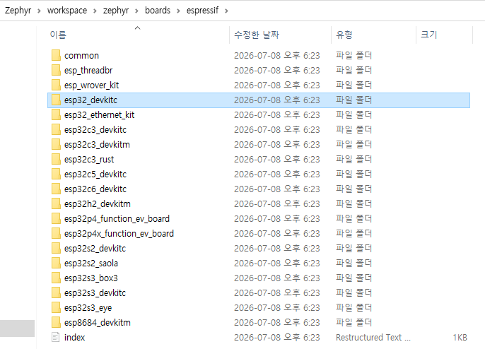
Now it is time to create a directory to store the board definition for the board we will use.
Instead of modifying the esp32_devkitc board provided by Zephyr directly, we will create a separate board directory to manage our custom board. This approach prevents our custom board files from being affected by future Zephyr updates and makes maintenance easier.
To do this, create the my_boards/boards/skpang directory, copy the esp32_devkitc directory into it, and rename the copied directory to skpang_esp32_can.
The resulting directory structure is as follows:
workspace
└── my_boards
    └── boards
        └── skpang
            └── skpang_esp32_can
From this point on, we will modify the necessary files in the skpang_esp32_can directory one by one to create a board definition that matches the ESP32 CAN Board.
Modifying the Board Configuration
The esp32_devkitc directory contains the following files.
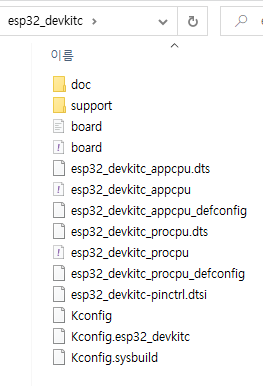
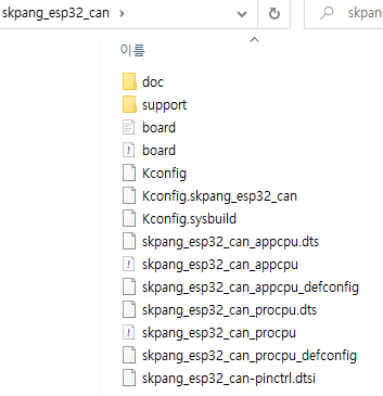
The skpang_esp32_can directory that we created contains the same files. We will replace all occurrences of esp32_devkitc with skpang_esp32_can in the file names and file contents.
After completing the replacements, the directory will look as follows:
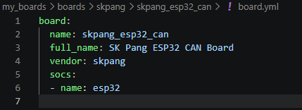
Modifying board.yml
First, we will modify the board.yml file.
This file defines basic information about the board, such as the board name, vendor, and supported SoC.
Modify board.yml as follows:
Modifying Kconfig
Next, we will modify the Kconfig-related files.
In Zephyr, Kconfig is used to define board-related configuration options and default settings. When adding a new board, the Kconfig definitions must also be updated accordingly.
For the new board, the existing esp32_devkitc definitions need to be changed to skpang_esp32_can.
In this exercise, we will modify the following two files:
KconfigKconfig.skpang_esp32_can
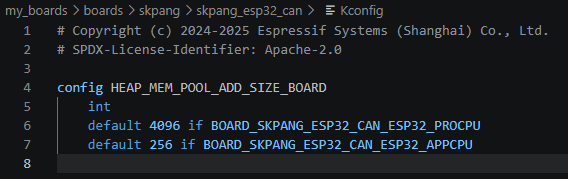
Kconfig
The Kconfig file defines board-specific Kconfig settings used by the current board.
Since the board name has changed, the corresponding board configuration symbols must also be updated.
Modify the file as follows:
Kconfig.skpang_esp32_can
Next, we will modify the Kconfig.skpang_esp32_can file.
The Kconfig.skpang_esp32_can file defines the board name and the ESP32 SoC configuration used by the board. Since the board name has been changed, the related configuration symbols must also be updated to match the new board name.
Modify the file as follows:
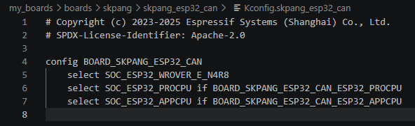
Once these modifications are complete, Zephyr will recognize skpang_esp32_can as a separate board instead of the original esp32_devkitc.
Now that the basic board configuration is complete, we will move on to the YAML files to define the board’s supported features and related information.
Modifying YAML Files
Next, we will modify the YAML files.
YAML files define information such as the architectures and SoCs supported by the board, toolchain, RAM, and Flash memory. This information is also used when running west boards or searching for boards in Visual Studio Code.
In this exercise, we will modify the following two files:
skpang_esp32_can_appcpu.yamlskpang_esp32_can_procpu.yaml
Both files are based on the original esp32_devkitc definitions, so we will update the board names to match the new skpang_esp32_can board.
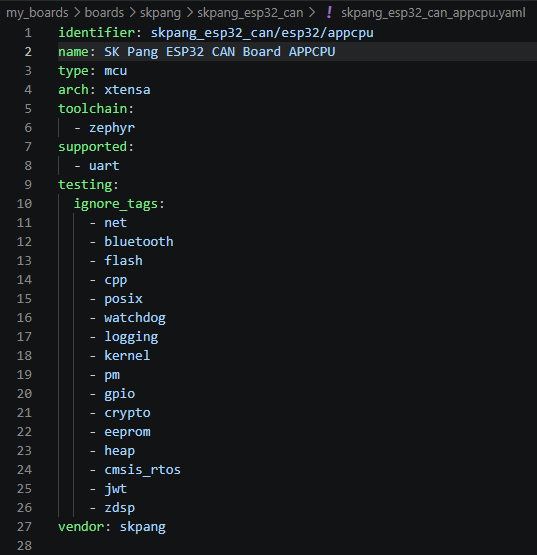
Modifying skpang_esp32_can_appcpu.yaml
First, we will modify the skpang_esp32_can_appcpu.yaml file.
This file contains the board configuration for the Application CPU (App CPU).
Change the board name to skpang_esp32_can_appcpu as shown below.
Next, we will modify the skpang_esp32_can_procpu.yaml file.
This file defines the board configuration for the ESP32 Primary CPU (Pro CPU).
As with the previous file, change the board name to skpang_esp32_can_procpu.
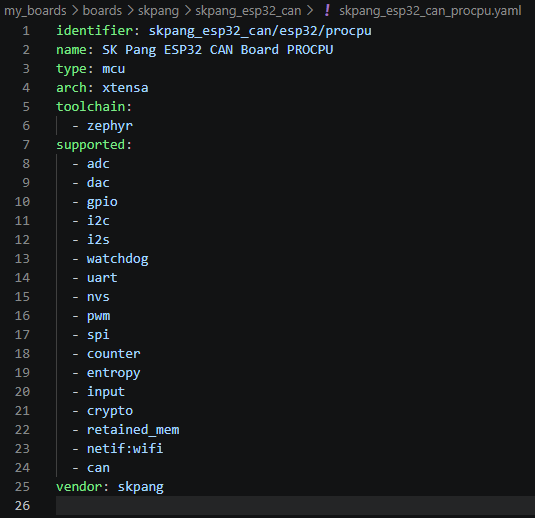
vendor: skpangSo far, we have completed the basic configuration required to register the new board with Zephyr. Next, we will modify the Devicetree (DTS) to reflect the actual hardware configuration of the ESP32 CAN Board.
Modifying the Devicetree (DTS)
Next, we will modify the Devicetree (DTS) files.
The Devicetree describes the hardware connected to the board so that Zephyr can understand how the MCU peripherals are configured. It defines hardware-related information such as which GPIO pins are connected, which LEDs are used, and which UART peripherals are enabled.
In this exercise, we will use the existing esp32_devkitc Devicetree as a base and modify it to match the hardware configuration of the ESP32 CAN Board.
Since the ESP32 is a dual-core MCU, separate DTS files are provided for the App CPU and Pro CPU. In this exercise, we will modify only the skpang_esp32_can_procpu.dts file, because the board will run on the Pro CPU.
First, we will check the RGB LED connections in the board schematic and reflect them in the Devicetree.
The schematic below shows which pins are connected to the RGB LED.
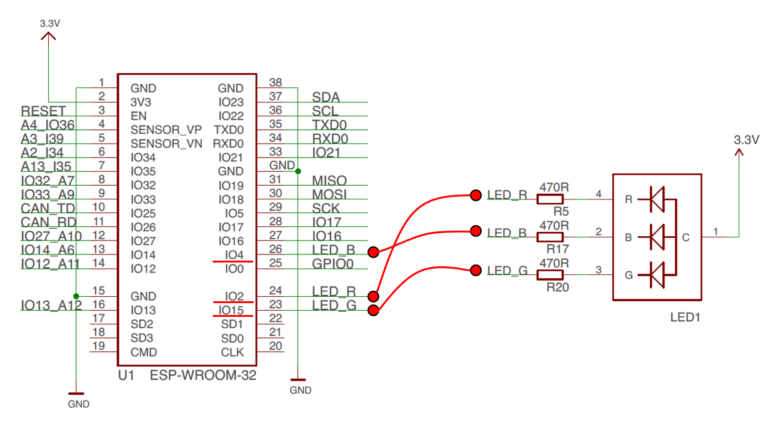
From the schematic, the RGB LED is connected to the ESP-WROOM-32 GPIO pins as follows:
- LED_R: IO2
- LED_G: IO15
- LED_B: IO4
We will add these GPIO definitions to the Devicetree so that Zephyr can control each color of the RGB LED.
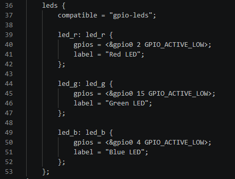
The aliases node in the Devicetree assigns convenient names to hardware devices. This allows the application to refer to the RGB LEDs using simple names such as led0, led1, and led2.
We will register each RGB LED in the aliases node as shown below.
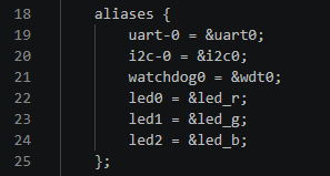
With these Devicetree modifications, the RGB LED on the ESP32 CAN Board is now defined in Zephyr.
Next, we will add the CAN interface to the Devicetree to continue configuring the hardware of the ESP32 CAN Board.
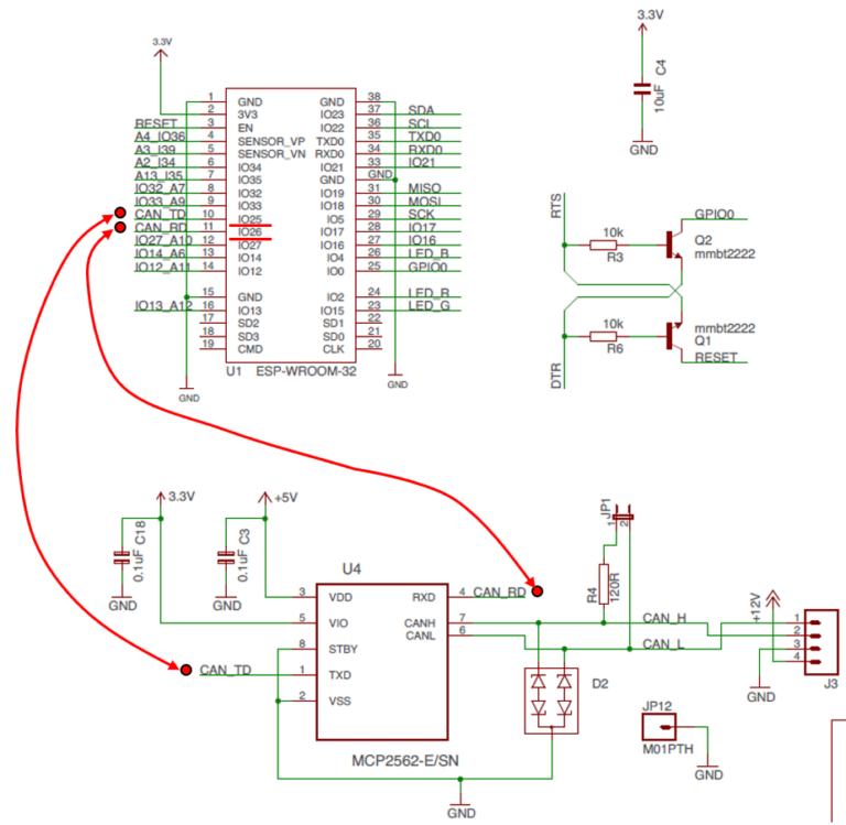
From the schematic below, we can see that CAN_TD is connected to IO25 and CAN_RD is connected to IO26.
Note
In the schematic, the CAN signals are labeled CAN_TD (CAN_TX) and CAN_RD (CAN_RX). From this point on, we will use CAN_TX and CAN_RX, following the naming convention used in Zephyr and ESP-IDF.
In Zephyr, pin configuration (Pin Multiplexing) and device configuration are managed separately. Therefore, to use the CAN interface, we first define the CAN pins in pinctrl.dtsi, and then enable the CAN device in the .dts file.
First, add the GPIO pins used for CAN to the skpang_esp32_can-pinctrl.dtsi file. On the ESP32, the CAN controller is provided under the name TWAI (Two-Wire Automotive Interface), so the related Devicetree node also uses the name twai.
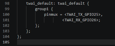
Next, enable the TWAI device in the skpang_esp32_can_procpu.dts file and connect it to the twai_default pin configuration defined above.
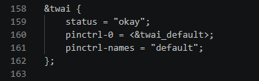
With this configuration, GPIO25 operates as the CAN transmit (TX) pin and GPIO26 as the CAN receive (RX) pin, allowing the CAN (TWAI) driver to be used from Zephyr.
Board Porting Summary
So far, we have created the new skpang_esp32_can board and modified its board definition and Devicetree to match the hardware configuration of the ESP32 CAN Board.
The main changes are summarized below:
- Created a new custom board
- Modified
board.yml - Modified Kconfig files
- Modified YAML files
- Added the RGB LED definitions
- Added the CAN (TWAI) interface
Zephyr can now recognize skpang_esp32_can as an independent board, providing the basic environment required to use the RGB LED and CAN interface.
Finally, let’s verify that Zephyr correctly recognizes the newly added board.
Run the following command to check whether the custom board has been successfully registered:
west boards --board-root D:\Zephyr\workspace\my_boards | findstr skpangIf the board porting has been completed successfully, skpang_esp32_can will appear as shown below.

The board porting process is now complete. Next, we will create an RGB LED application to verify that the newly created board works correctly with Zephyr.
Creating the RGB LED Application
Now, we will create a simple application to control the RGB LED.
In this exercise, the red LED will blink at 500 ms intervals. This allows us to verify that the RGB LED definitions added to the Devicetree are working correctly.
For this application, we will not create any additional threads. Instead, we will use a simple structure that controls the LED directly from the main() function.
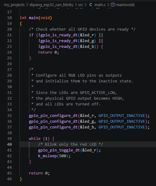
The main.c program is shown below.
Code Explanation
First, gpio_is_ready_dt() is used to check whether the GPIO devices associated with the RGB LEDs defined in the Devicetree are ready for use.
Next, gpio_pin_configure_dt() configures the GPIO pins for the Red, Green, and Blue LEDs as outputs and sets their initial state to OFF.
gpio_pin_configure_dt(&led_r, GPIO_OUTPUT_INACTIVE);
gpio_pin_configure_dt(&led_g, GPIO_OUTPUT_INACTIVE);
gpio_pin_configure_dt(&led_b, GPIO_OUTPUT_INACTIVE);
Because the RGB LEDs on this board are active-low, setting the pins to GPIO_OUTPUT_INACTIVE drives the actual GPIO outputs HIGH, which turns the LEDs off.
Finally, inside the while(1) loop, gpio_pin_toggle_dt() toggles the state of the red LED, and k_msleep(500) waits for 500 ms.
gpio_pin_toggle_dt(&led_r);
k_msleep(500);
As a result, the red LED repeatedly changes between ON and OFF every 500 ms.
The RGB LED application is now complete.
Next, we will build the project for the skpang_esp32_can board, flash the generated firmware to the ESP32 CAN Board, and verify its actual operation.
Build and Flash
Now, we will build the RGB LED application created in the previous section, flash it to the ESP32 CAN Board, and verify that it operates as expected.
Before starting the build, we need to create several files required to configure the application.
Creating Project Configuration Files
In this project, we will add or modify the following three files:
- CMakeLists.txt: Specifies the application source files to the Zephyr build system.
- prj.conf: Defines the Zephyr features and configuration options used by the application.
- CHANGELOG.md: Records project changes and development history.
CMakeLists.txt and prj.conf are basic files required to build a Zephyr application. CHANGELOG.md is not directly used during the build process, but we will include it to keep track of project changes and development history.
Creating CMakeLists.txt
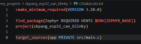
CMakeLists.txt tells the Zephyr build system which source files belong to the current project and should be included in the build.
Since this application uses only src/main.c, we will create the file as follows.
Creating prj.conf
The prj.conf file defines the Zephyr features and configuration options used by the application.
For this RGB LED application, we will enable the GPIO functionality and add the serial console settings so that the application status can be monitored through the console.
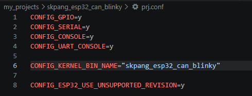
Here, CONFIG_KERNEL_BIN_NAME specifies the name used for the generated Zephyr binary file.
CONFIG_ESP32_USE_UNSUPPORTED_REVISION=y allows the application to run even when the detected ESP32 chip revision is not included in the revision range officially supported by the current Zephyr configuration.
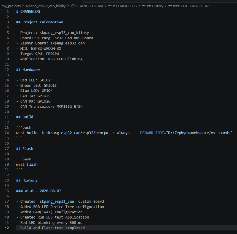
Creating CHANGELOG.md
This file is not required for the Zephyr build process. However, we will use it to keep track of version changes as new features are added or the application is modified.
The contents are as follows:
The project configuration files are now complete. Next, we will build the application for the skpang_esp32_can board created earlier.
Build
Now, we will build the application.
The build command can be copied from the Build section of the CHANGELOG.md file created earlier and pasted into the Visual Studio Code terminal.
The command is as follows:

Since this command does not specify a separate application directory, first move to the skpang_esp32_can_blinky project directory and then run the command.
If the build is successful, output similar to the following will be displayed.
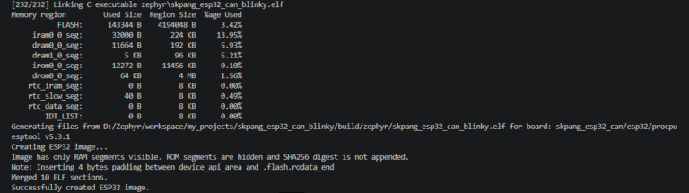
When the build completes successfully, the following message appears near the end of the output:
Successfully created ESP32 image.In addition, because the firmware name was specified in prj.conf as follows:
CONFIG_KERNEL_BIN_NAME="skpang_esp32_can_blinky"the build process generates an ELF file with the same project name.
build/zephyr/skpang_esp32_can_blinky.elfThis confirms that the application has been successfully built for the skpang_esp32_can board.
Next, we will flash the generated firmware to the ESP32 CAN Board.
Flash
The flash command can also be copied from the .md file. However, since this command does not require any special options, it is usually more convenient to simply type west flash directly in the terminal.
Run the following command:
west flashWhen west flash is executed, output similar to the following will appear.
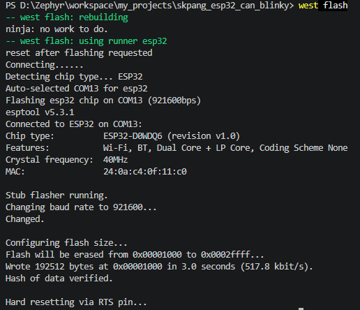
If the flashing process proceeds normally, west automatically detects the connected ESP32 and uses esptool to write the firmware to the board’s Flash memory.
In the example above, the ESP32 was successfully detected on COM13. After the firmware is written, the following messages are displayed:
Hash of data verified.

Hard resetting via RTS pin...
Hash of data verified. indicates that the data written to Flash has been successfully verified. The board is then automatically reset, and the newly flashed firmware starts running.
Therefore, the built firmware can be downloaded to the board with a single command, without requiring a separate programmer or a manual reset procedure.
Test Results
After flashing the firmware, the board automatically resets and starts running the application.
As a result, the red LED of the built-in RGB LED on the ESP32 CAN Board blinks correctly at 500 ms intervals. The Green and Blue LEDs remain OFF.
This confirms that both the RGB LED GPIO configuration in the Devicetree and the GPIO control in the application are working correctly.
It also verifies that the entire process—from custom board recognition and build to flashing and actual firmware execution—has been completed successfully.
Conclusion
In this exercise, we created a new skpang_esp32_can board for the SK Pang ESP32 CAN Board, using the officially supported esp32_devkitc board as a reference.
After creating the new board, we modified the board-related files, including board.yml, Kconfig, and YAML files. We also updated the Devicetree to configure the RGB LED and CAN (TWAI) interface according to the actual hardware.
We then created a simple RGB LED application, built and flashed the firmware, and confirmed that the red LED blinks correctly at 500 ms intervals.
The important point of this exercise is not simply blinking an LED, but experiencing the complete process of creating a new custom board for actual hardware based on an existing Zephyr board definition and running an application on it.
We now have a basic environment for using the ESP32 CAN Board with Zephyr. In the next exercises, we will use this ported board to explore UART, CAN, and Wi-Fi step by step.
“Zephyr ESP32 Tutorial #1 – ESP32 CAN Board Porting and RGB LED Control”에 대한 1개의 생각