Introduction
This is the fourth article in the Zephyr ESP tutorial series.
In the previous articles, we practiced connecting the ESP32 Wi-Fi module to an AP on a Wi-Fi network and obtaining an IP address. From this article, we will move one step further and practice actually exchanging data between an embedded device and a PC over a Wi-Fi network.
There are several ways to communicate over a Wi-Fi network, but the first communication method we will practice is UDP. Compared with TCP, UDP operates in a simpler manner, making it possible to implement data transmission over a Wi-Fi network with relatively simple code.
In this exercise, we will first transmit UDP data from the ESP32 to the PC, and then transmit UDP data from the PC to the ESP32. Through this process, we will go beyond simply connecting to a Wi-Fi AP and obtaining an IP address, and verify actual bidirectional data communication over a Wi-Fi network.
We will also examine how to create a socket and use it for UDP communication in Zephyr, and use simple Python programs on the PC to exchange data with the ESP32.
Creating the Project and Configuration Files
Let’s create a new project and prepare the configuration files.
This is a task that needs to be repeated whenever we start a new project.
The reason we continue to cover the same process described in previous articles is that although some details may differ from project to project, repeatedly going through this process—even when there are no major differences—is a good way to become familiar with the basic workflow for starting a Zephyr project.
Creating the Project
Copy the previous project, skpang_esp32_can_wificonnect, and create a new folder named skpang_esp32_can_wifiudp.
The newly created folder is shown below.
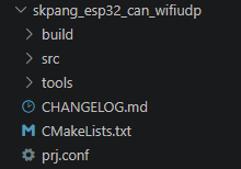
Unlike the previous project, a new folder named tools has been added.
This folder was created to store the Python programs for the UDP server and client that will later be used for UDP communication on the PC.
We will explain this again later.
Creating the Configuration Files
As shown in the folder above, CMakeLists.txt, prj.conf, and CHANGELOG.md need to be modified to match the newly created project.
CMakeLists.txt
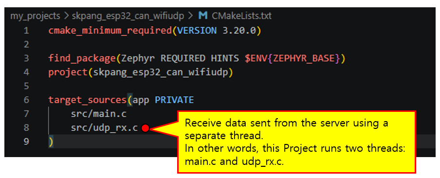
The figure above shows the contents of CMakeLists.txt.
The difference from the previous project is that src/udp_rx.c has been added to the target_sources section.
As we will explain in detail in the program implementation section, this project transmits and receives data using UDP communication.
Therefore, the UDP data reception code is separated from main.c and implemented in udp_rx.c, where it runs in a separate thread.
prj.conf
The figure below shows the prj.conf file. Compared with the previous Wi-Fi Connect project, there are two major changes.
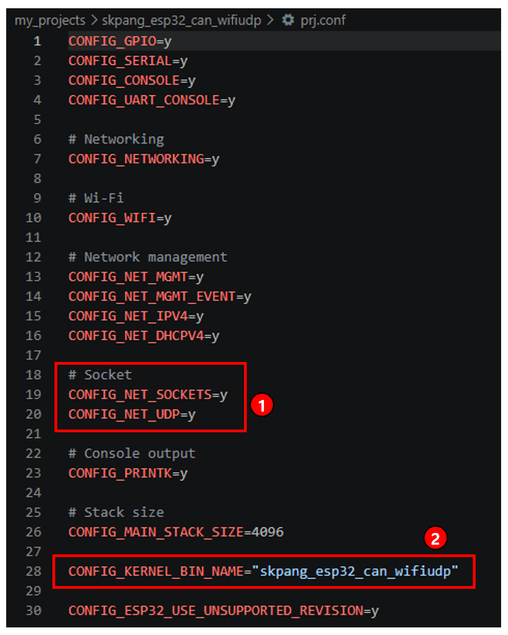
① These are the socket-related settings added for UDP communication.
CONFIG_NET_SOCKETS=y enables the Socket API in Zephyr. In this project, sockets are used for UDP data transmission and reception, so this setting is required to allow the program to create and use sockets.
CONFIG_NET_UDP=y enables the UDP protocol. In the previous Wi-Fi Connect project, the ESP32 only connected to an AP and obtained an IP address, so this setting was not required. In this project, however, actual UDP data is transmitted and received, so UDP support has been added.
In other words, by adding socket and UDP functionality on top of the existing Wi-Fi and network configuration, the ESP32 can go beyond simply connecting to a Wi-Fi network and actually transmit and receive data.
② This setting specifies the name of the generated Zephyr executable files.
By setting
CONFIG_KERNEL_BIN_NAME="skpang_esp32_can_wifiudp"
the bin, hex, and elf files generated during the build process are named skpang_esp32_can_wifiudp instead of the default zephyr.
This setting does not directly affect program operation, but it makes it easier to identify which project the generated firmware files belong to when managing multiple projects.
The remaining Wi-Fi, Network Management, IPv4, and DHCP settings are unchanged from those used in the previous Wi-Fi Connect project.
CHANGELOG.md
Create the CHANGELOG.md file as shown below.
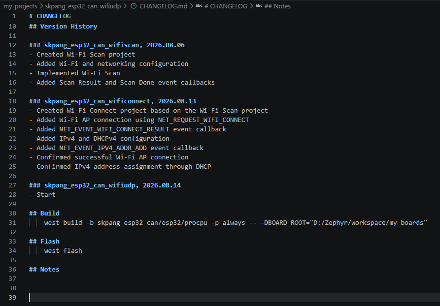
The CHANGELOG.md file continuously records the change history of the projects developed so far. The names of the previous Wi-Fi Scan and Wi-Fi Connect projects are kept as they are, and the newly created skpang_esp32_can_wifiudp project has been added below them.
Since the project has just been created, only the Start entry is recorded in the change history for now. As we proceed with the exercise by implementing UDP transmission and reception, major changes will be added one by one.
By maintaining CHANGELOG.md whenever a new project is started, we can later trace which features were added and how the project evolved during development.
What is UDP Communication?
Overview of UDP Communication
UDP (User Datagram Protocol) is one of the communication protocols used to transmit data over a network.
Two of the most widely used transport protocols in network communication are TCP and UDP. TCP establishes a connection with the other side and communicates while verifying that the data has been delivered successfully. Therefore, it provides reliable data transmission, but requires additional processes such as connection establishment and data verification.
In contrast, UDP sends data immediately without establishing a separate connection with the other side. Basically, it does not provide mechanisms to verify whether the transmitted data has successfully reached the destination or to guarantee the order of the transmitted data.
Because of these characteristics, UDP has a simpler structure than TCP and allows data to be transmitted and received with relatively simple code. Therefore, it is well suited for a first exercise in actual data communication over a Wi-Fi network.
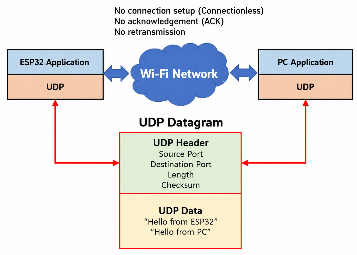
The figure below shows the basic structure of UDP communication. A UDP header is added to the data sent by the application, forming a single UDP datagram. A datagram can be considered an independent unit of data transmitted at one time using UDP.
The UDP header contains the source and destination port numbers, the length of the datagram, and a checksum for error checking.
IP Addresses and Ports
To transmit data using UDP, you need to know the IP address and port number of the device that will receive the data.
An IP address identifies a device connected to a network, while a port number identifies the program or communication service on that device that will receive the data.
For example, suppose the IP address of the PC is:
192.168.0.10
If a UDP server running on the PC uses port 5000, the ESP32 transmits data using the following two pieces of information:
- Destination IP Address:
192.168.0.10 - Destination Port:
5000
In other words, the IP address determines which device the data will be sent to, while the port number determines which program on that device will receive the data.
UDP Server and Client
Unlike TCP, UDP does not establish a connection between a server and a client before communication begins. Therefore, the distinction between a server and a client in UDP is not as strict as it is in TCP.
In general, the side that opens a specific port and waits for data can be called a UDP server, while the side that sends data to that IP address and port can be called a UDP client.
In this exercise, the ESP32 and PC are configured to exchange UDP data with each other.
First, we will transmit data from the ESP32 to the UDP server on the PC to verify ESP32 → PC communication. Then, we will transmit data from the PC to the ESP32 to verify PC → ESP32 communication.
Through these steps, we will ultimately practice bidirectional UDP communication as follows:
ESP32 ↔ PC Bidirectional UDP Communication
In an actual UDP communication program, sockets are used to implement these operations. In the next section, we will use Zephyr’s Socket API to implement a program that transmits and receives UDP data on the ESP32.
Implementing the ESP32 Program
Overview
Now, let’s implement the program that performs UDP communication on the ESP32.
In this project, we will use the previously implemented Wi-Fi Connect functionality to first connect the ESP32 to a Wi-Fi AP and obtain an IP address.
After that, a UDP socket is created using Zephyr’s Socket API to transmit and receive data with the PC.
The program is divided into two main parts.
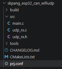
In main.c, the ESP32 connects to the Wi-Fi AP, confirms that an IP address has been assigned, creates a UDP socket, and transmits data to the PC. UDP data reception is handled by a separate thread implemented in udp_rx.c.
The following shows the structure of the src folder, which contains main.c, udp_rx.c, and udp_rx.h.
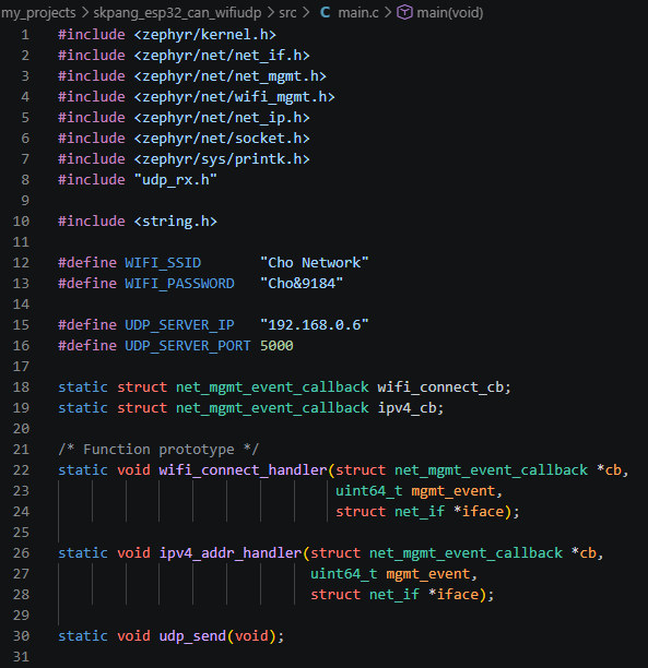
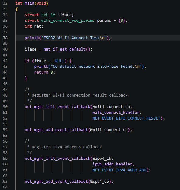
When the program starts, it first obtains the default network interface using net_if_get_default() and registers event callbacks to check the Wi-Fi connection result and IPv4 address assignment.
It then connects to the Wi-Fi AP with the specified SSID using the NET_REQUEST_WIFI_CONNECT request.
When the Wi-Fi connection is completed, the NET_EVENT_WIFI_CONNECT_RESULT event occurs. When an IPv4 address is assigned through DHCP, the NET_EVENT_IPV4_ADDR_ADD event occurs.
Since this process was covered in detail in the previous Wi-Fi Connect exercise, the repeated parts will not be explained again in detail here.
However, before UDP communication can begin, the ESP32 must first connect successfully to the Wi-Fi network and obtain an IP address. Therefore, this process is also performed in this project before creating the UDP socket.
The overall program flow is as follows:
Connect to Wi-Fi AP → Obtain IPv4 Address → Create UDP Socket → Transmit UDP Data to PC
UDP data reception is handled in a separate thread.
Create UDP Socket → Bind to Port → Wait for Data → Receive UDP Data
The complete main.c program is shown below.
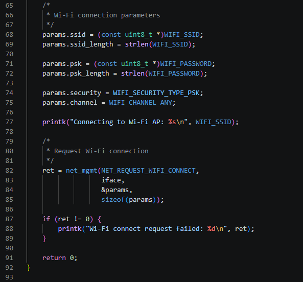
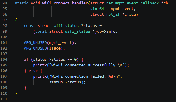
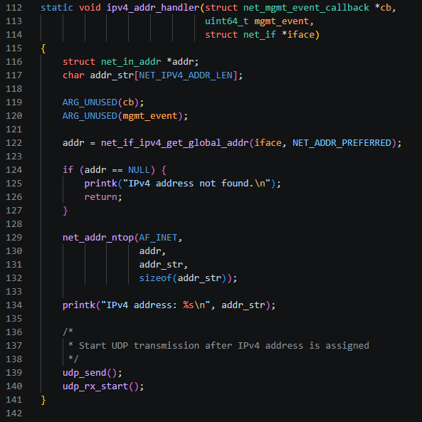
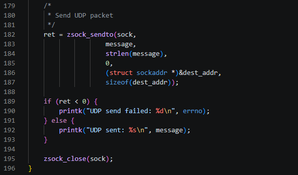
Now, let’s take a closer look at the UDP transmission and reception performed after the Wi-Fi network connection has been established.
UDP Transmit Program
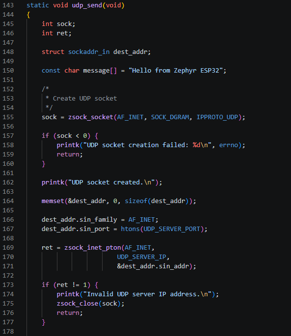
The UDP transmit program is implemented in the udp_send() function in main.c, as shown in the code above.
The details are as follows.
To transmit UDP data from the ESP32 to the PC, the IP address and port number of the PC that will receive the data must first be specified.
For this purpose, a sockaddr_in structure is used to configure the destination address. This structure stores information such as the address family, destination port, and destination IP address.
The socket functions used in this exercise are part of Zephyr’s BSD Sockets compatible API. Detailed descriptions of these functions can be found in the official Zephyr API documentation .
The UDP socket is created using the zsock_socket() function.
sock = zsock_socket(AF_INET, SOCK_DGRAM, IPPROTO_UDP);AF_INET indicates that IPv4 is used, while SOCK_DGRAM specifies a datagram socket, that is, a UDP socket. IPPROTO_UDP explicitly specifies UDP as the protocol to be used.
Once the socket has been created successfully, the PC’s IP address and port number are configured.
dest_addr.sin_family = AF_INET;
dest_addr.sin_port = htons(UDP_SERVER_PORT);

ret = zsock_inet_pton(AF_INET,
                      UDP_SERVER_IP,
                      &dest_addr.sin_addr);
sin_family is set to AF_INET, which indicates IPv4, while sin_port specifies the port number used by the UDP server on the PC.
htons() converts the port number value used by the CPU into the byte order used by the network.
Because network byte order uses Big Endian, htons() converts a 16-bit port number from Host Byte Order to Network Byte Order.
Here, htons stands for Host TO Network Short.
zsock_inet_pton() converts an IP address represented as a string, such as "192.168.x.x", into the binary format used by the network and stores it in addr.sin_addr.
Here, pton stands for Presentation TO Network.
Once the destination address has been configured, UDP data can be transmitted using the zsock_sendto() function.
ret = zsock_sendto(sock,
                   message,
                   strlen(message),
                   0,
                   (struct sockaddr *)&dest_addr,
                   sizeof(dest_addr));
Here:
sock → Socket used for UDP communicationmessage → Data to be transmittedstrlen(message) → Length of the data to be transmitted0 → No additional flags are useddest_addr → Destination IP address and port informationsizeof(dest_addr) → Size of the destination address structure
When zsock_sendto() is called, the data to be transmitted is passed together with dest_addr, which contains the destination IP address and port.
Unlike TCP, UDP does not establish a connection with the other side in advance. Therefore, data can be transmitted directly using zsock_sendto() without a separate connection process.
The data transmitted by a single call to zsock_sendto() becomes one UDP datagram.
UDP Receive Program
UDP data reception is separated from main.c and handled by a separate thread in udp_rx.c.
For UDP transmission, data can simply be sent by calling zsock_sendto() whenever necessary. However, the receive program must continuously wait for incoming data because it cannot know when the PC will transmit data.
Therefore, in this project, a separate thread is created for UDP reception, and this thread waits until UDP data arrives.
For this purpose, the following two files have been added to the src folder:
udp_rx.c: Implements the actual UDP data reception function and thread.udp_rx.h: Defines the declarations required to use the UDP reception function inmain.c.
The basic operation of the UDP receive program is as follows:
Create UDP Socket → Set Local IP/Port → Bind Socket → Wait for Data → Receive UDP Data
In the transmit program, the destination IP address and port are specified each time zsock_sendto() is called.
In contrast, the receive program must first specify which port on the ESP32 will receive incoming UDP data. For this purpose, the local address and port are configured, and the created socket is bound to them using zsock_bind().
Once the bind operation is complete, zsock_recvfrom() waits for UDP datagrams transmitted from the PC.
Now, let’s examine the contents of udp_rx.h and udp_rx.c in order.
The code for udp_rx.h is shown below.
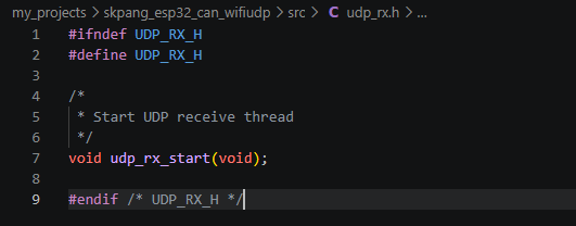
udp_rx.h is a header file that declares the function prototype required to use the UDP receive functionality from other source files.
In this program, the following function is declared to start the UDP receive functionality implemented in udp_rx.c.
void udp_rx_start(void);
In main.c, after including udp_rx.h, the UDP receive thread can be started by calling udp_rx_start().
Next, let’s look at udp_rx.c.
The following is the declaration section.
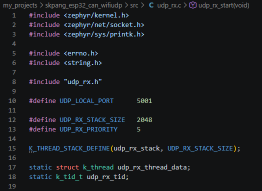
zephyr/kernel.h is required to use Zephyr kernel features such as threads, while zephyr/net/socket.h is required to use APIs such as UDP sockets.
Next, define the values required for the UDP receive port and thread.
#define UDP_LOCAL_PORT      5001

#define UDP_RX_STACK_SIZE   2048
#define UDP_RX_PRIORITY     5
UDP_LOCAL_PORT specifies the port number on which the ESP32 receives UDP data. In this program, port 5001 is used.
Therefore, when transmitting UDP data from the PC to the ESP32, the destination port must be set to 5001 together with the ESP32’s IP address.
UDP_RX_STACK_SIZE specifies the stack size used by the UDP receive thread, while UDP_RX_PRIORITY specifies the priority of the thread.
Next, the stack and thread-related variables required to create the UDP receive thread are declared.
K_THREAD_STACK_DEFINE(udp_rx_stack, UDP_RX_STACK_SIZE);

static struct k_thread udp_rx_thread_data;
static k_tid_t udp_rx_tid;
K_THREAD_STACK_DEFINE() creates the stack area used by the UDP receive thread.
udp_rx_thread_data stores the control information for the created thread, while udp_rx_tid stores the ID of the created thread.
In this way, the port used for UDP reception and the items required to run the thread are prepared in advance.
Next is udp_rx_thread(), the function that actually handles UDP data reception.
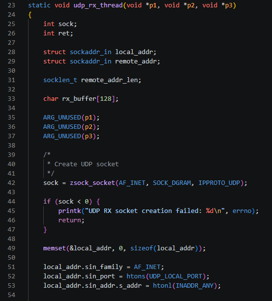
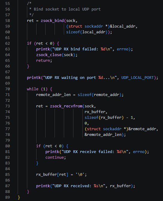
Variables Required for UDP Reception
First, declare the variables required to receive UDP data.
int sock;
int ret;

struct sockaddr_in local_addr;
struct sockaddr_in remote_addr;

socklen_t remote_addr_len;

char rx_buffer[128];
sock is the socket descriptor used to identify the created UDP socket, while ret is used to check the result of each socket function call.
Two sockaddr_in structures are used here.
local_addr is used to configure the UDP receive address information of the ESP32 itself. In particular, it specifies which port on the ESP32 will receive UDP data.
In contrast, remote_addr is used to store the address information of the device that sent the UDP data. When zsock_recvfrom() is called later, the sender’s IP address and port information are stored in this structure.
remote_addr_len is used to pass the size of the remote_addr structure, while rx_buffer is the buffer that stores the UDP data actually received.
A thread function can receive three parameters, p1, p2, and p3, but they are not used in this program, so they are handled as follows.
ARG_UNUSED(p1);
ARG_UNUSED(p2);
ARG_UNUSED(p3);
Creating the UDP Socket
On the receive side, just as on the transmit side, a UDP socket is created first.
sock = zsock_socket(AF_INET, SOCK_DGRAM, IPPROTO_UDP);AF_INET indicates IPv4, SOCK_DGRAM specifies a datagram socket, and IPPROTO_UDP indicates that the UDP protocol is used.
If socket creation fails, a negative value is returned. Therefore, the result is checked, and the thread is terminated if socket creation fails.
if (sock < 0) {
    printk("UDP RX socket creation failed: %d\n", errno);
    return;
}
Setting the Local Address and Port
Next, configure the local address on which the ESP32 will receive UDP data.
memset(&local_addr, 0, sizeof(local_addr));

local_addr.sin_family = AF_INET;
local_addr.sin_port = htons(UDP_LOCAL_PORT);
local_addr.sin_addr.s_addr = htonl(INADDR_ANY);
First, memset() initializes the local_addr structure to zero.
sin_family is set to AF_INET, which indicates IPv4, and sin_port is set to port 5001 using the previously defined UDP_LOCAL_PORT.
Here, INADDR_ANY means that instead of specifying one particular local IP address, the UDP socket can receive data through any available local IPv4 address.
Therefore, the socket and port have not yet been bound at this point. Only the local address information that the ESP32 will use has been prepared in local_addr.
Binding the Socket to the Local Port
zsock_bind() connects the prepared local_addr to the actual UDP socket.
ret = zsock_bind(sock,
                 (struct sockaddr *)&local_addr,
                 sizeof(local_addr));
This can be understood more easily by comparing it with zsock_sendto(), which was used for transmission.
On the transmit side, when zsock_sendto() is called, the socket and destination address are specified together to transmit a datagram.
On the receive side, zsock_bind() is first used to bind the local address and port to the created socket.
In other words:
zsock_socket()
      ↓
   UDP Socket ───┐
                 ├─ zsock_bind()
Local Address ───┘
  └─ Port 5001
      ↓
Receive UDP data arriving
at Port 5001 through this socket
Now the socket is ready to receive UDP datagrams arriving at port 5001 on the ESP32.
Receiving UDP Data
Once zsock_bind() is complete, the ESP32 is ready to receive UDP data arriving at the specified port.
Inside the following while (1) loop, zsock_recvfrom() is repeatedly called so that UDP data can be received continuously.
First, in the following code, remote_addr_len is set to the size of the remote_addr structure.
remote_addr_len = sizeof(remote_addr);As explained earlier, remote_addr is a structure used to store the address information of the device that sent the UDP data.
Next, zsock_recvfrom() is called.
ret = zsock_recvfrom(sock,
                     rx_buffer,
                     sizeof(rx_buffer) - 1,
                     0,
                     (struct sockaddr *)&remote_addr,
                     &remote_addr_len);
The meaning of each argument is as follows:
sock→ UDP socket created earlier and bound to port 5001rx_buffer→ Buffer where the received data is storedsizeof(rx_buffer) - 1→ Maximum amount of data that can be received at one time0→ No additional flags are usedremote_addr→ Stores the IP address and port information of the device that sent the dataremote_addr_len→ Size of the sender address structure
If no UDP datagram has arrived, zsock_recvfrom() waits until data is received. When a UDP datagram is transmitted from the PC to port 5001 of the ESP32, zsock_recvfrom() receives the data, stores it in rx_buffer, and returns the number of bytes received in ret.
Therefore, for example, if the PC transmits the 13-byte string "Hello from PC", ret will be 13 when the data is received successfully.
Checking for Receive Errors
The following code checks the result of zsock_recvfrom().
if (ret < 0) {
    printk("UDP RX receive failed: %d\n", errno);
    continue;
}
If ret is negative, an error occurred during the receive operation.
Even if an error occurs, the thread is not terminated. Instead, continue returns execution to the beginning of the while (1) loop, where the program waits for the next UDP data.
Completing the Received Data as a String
When data is received successfully, the following code is executed.
rx_buffer[ret] = '\0';zsock_recvfrom() returns the number of bytes received in ret, but it does not automatically append '\0', which indicates the end of a C string.
Therefore, '\0' is inserted immediately after the received data so that rx_buffer becomes a valid C string.
Earlier, the receive size was specified as
sizeof(rx_buffer) - 1to leave one byte of space for storing this '\0'.
Finally, the received string is printed.
printk("UDP RX received: %s\n", rx_buffer);Therefore, when "Hello from PC" is transmitted from the PC, the following output can be seen on the ESP32 serial terminal.
UDP RX received: Hello from PCAfter this process is complete, execution returns to the beginning of the while (1) loop and calls zsock_recvfrom() again. In this way, the UDP receive thread continuously waits for UDP datagrams arriving at Port 5001.
The overall flow can be summarized as follows.
while (1)
    ↓
zsock_recvfrom()
    ↓
Wait for a UDP Datagram
    ↓
Receive UDP Data
    ↓
Store in rx_buffer
    ↓
Append '\0'
    ↓
Print Received Data
    ↓
Call zsock_recvfrom() Again
An especially important point here is that zsock_recvfrom() can obtain not only the data itself, but also information about who sent the data through remote_addr.
In the current program, only the received string is printed. However, remote_addr can later be used to check the sender’s IP address and port.
The final part of udp_rx.c is the function that starts this thread.
It is shown below.
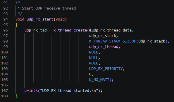
Since this part was covered in sufficient detail in the Zephyr Thread exercise, we will not explain it again here.
Now, both the UDP transmit and receive programs required for UDP communication on the ESP32 are ready. In the next section, we will prepare the UDP server and client programs on the PC to actually exchange data with the ESP32.
Preparing the PC UDP Server and Client
To transmit and receive UDP data with the ESP32, we will use simple Python programs on the PC.
We prepared a UDP Server program to receive UDP data transmitted from the ESP32 to the PC, and a UDP Client program to transmit UDP data from the PC to the ESP32.
Both programs are stored in the project’s tools folder.
UDP Server
The following is the Python code for the UDP Server.
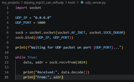
The program performs the following operations:
- Opens a specified port on the PC and waits for data
- Receives UDP data transmitted from the ESP32
- Displays the received data on the screen
UDP Client
The following is the Python code for the UDP Client.
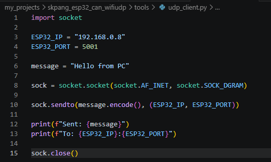
The program performs the following operations:
- Specifies the ESP32’s IP address and port
5001 - Transmits UDP data such as
"Hello from PC"
The PC program is a simple program that uses Python’s socket module. Since the purpose of this article is to implement UDP communication on the ESP32 using Zephyr, a detailed explanation of the Python code will be omitted.
Windows Firewall Configuration
To transmit UDP data from the ESP32 to the PC, Windows Firewall must allow network traffic arriving at the port used by the UDP Server on the PC.
In this exercise, the PC UDP Server uses port 5000, so Windows Defender Firewall is configured to allow inbound traffic on UDP port 5000.
Run Windows PowerShell as an administrator and enter the following command.
New-NetFirewallRule -DisplayName "UDP 5000" -Direction Inbound -Protocol UDP -LocalPort 5000 -Action AllowThis command adds an inbound rule named UDP 5000 to Windows Defender Firewall, allowing UDP data arriving at port 5000.
The communication directions used in this exercise can be summarized as follows.
ESP32
  |
  | UDP Datagram
  | Destination Port : 5000
  ▼
Windows Firewall
  |
  | Inbound UDP 5000 Allow
  ▼
udp_server.py
  |
  ▼
Receive UDP Data
Therefore, even if the UDP program on the ESP32 is operating correctly, if data is not received on the PC, you should also check whether the UDP Server’s port number and the Windows Firewall inbound rule are configured correctly.
Now that all preparations are complete, in the next section we will use these two programs to verify that UDP data is actually transmitted and received in both directions: ESP32 → PC and PC → ESP32.
Building and Verifying the Results
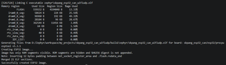
Now that all the programs are ready, let’s build the project.
As before, copy the command specified in the Build section of CHANGELOG.md and run it from the project directory.
If a message like the one below is displayed, you can confirm that the build was completed successfully.
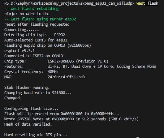
Next, download the program to the target board using the west flash command and run it.
If a message like the one below is displayed, the download was successful.
The console output messages were checked using Docklight.
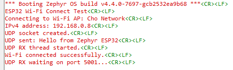
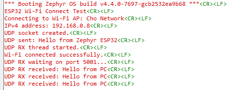
From the console output, we can confirm that the ESP32 successfully connected to the Wi-Fi AP and obtained an IPv4 address.
We can also see that the UDP socket was created successfully, the "Hello from Zephyr ESP32" data was transmitted, and the UDP receive thread is waiting for incoming UDP data on port 5001.
Now, let’s verify that the UDP data transmitted from the ESP32 is actually received by the PC.
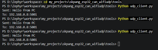
First, run the udp_server.py Python program and check whether the message sent from the ESP32 is received by the PC.
The ESP32 transmit program sends the data once during boot. Therefore, after starting udp_server.py, closing and reopening the connection in Docklight resets the ESP32 and causes it to transmit the data again. Of course, if the board has a Reset button, you can simply press it. Since our board does not have a Reset button, the reset was performed through the Docklight UART connection.
When udp_server.py is run on the PC, a message like the one below is displayed, and the program waits for incoming data from the ESP32.


Conclusion
In this exercise, we used the previously implemented Wi-Fi Connect project as a foundation and practiced actual UDP data transmission and reception between the ESP32 and a PC.
In the previous exercise, we verified that the ESP32 could connect to a Wi-Fi AP and obtain an IP address through DHCP. This time, we went one step further and implemented actual network data communication using the assigned IP address.
On the ESP32, we used Zephyr’s Socket API to create a UDP socket and transmitted UDP datagrams to the PC using zsock_sendto(). We also created a receive socket in a separate thread, bound it to a local port, and received UDP datagrams transmitted from the PC using zsock_recvfrom().
On the PC, simple Python UDP Server and Client programs were used to verify data transmission in both directions: ESP32 → PC and PC → ESP32.
Through this exercise, we were able to examine not only the connectionless characteristics of UDP and the meaning of a datagram, but also IP addresses, ports, sockets, bind operations, and the overall flow of data transmission and reception through an actual program.
Most importantly, we confirmed that network communication is not complete simply because a device has connected to a Wi-Fi AP and obtained an IP address. Actual communication is achieved when data is exchanged between applications using a protocol such as UDP.
For further study, Zephyr also provides an official Echo Server sample that demonstrates UDP and TCP communication using the Socket API.
With this, basic UDP communication between the ESP32 and PC has been completed. In the next exercise, we will examine TCP, which has different characteristics from UDP, and compare the two protocols through an actual implementation.