Introduction
In the previous article, we used Wi-Fi Scan to discover nearby APs (Access Points) and examined how Zephyr’s Wi-Fi Scan process operates based on events and callbacks.
In this article, we will take the next step and practice connecting the Zephyr ESP32 to a Wi-Fi AP. We will configure an AP and connect the ESP32 to it, then verify that an IP address is successfully assigned.
To connect to a Wi-Fi AP, connection information such as the SSID and password must first be configured, and a connection request must be made through Zephyr’s Network Management API. As with Wi-Fi Scan, the connection process is handled asynchronously based on events, so the connection result is checked through a callback.
Simply connecting to the AP is not enough. We will also verify that an IP address is successfully assigned to the ESP32 through DHCP.
The goal of this exercise is to confirm the following sequence:
AP Connection Request → Wi-Fi Connection Event → DHCP → IP Address Assignment
Once this process works successfully, the ESP32 has completed the basic preparation required to participate in a Wi-Fi network. From there, we can move on to actual network communication exercises using UDP, TCP, HTTP, MQTT, and other protocols.
Understanding the Wi-Fi AP Connection Process
In the previous exercise, Wi-Fi Scan was used to discover APs (Access Points) around the ESP32. Through the scan, we were able to obtain information such as the SSID, channel, RSSI, and security type, but the ESP32 had not yet joined the network.
In this exercise, we will select one of the discovered APs and actually connect to it.
To connect to a Wi-Fi AP, the following information is generally required:
- SSID: The name of the Wi-Fi AP to connect to
- Password: The Wi-Fi password
- Security: The security method, such as WPA2
Using this information, we request an AP connection through Zephyr, and the ESP32’s Wi-Fi driver performs the actual connection process.
More detailed information about Zephyr’s Wi-Fi connection and management features can be found in the official Zephyr Wi-Fi Management documentation.
Zephyr Wi-Fi Management Official Documentation
The official documentation is useful for understanding the functions of each API and event. However, to understand the actual AP connection process, it is also necessary to examine the order in which these APIs and events are used together.
The following diagram shows the overall process from requesting an AP connection to receiving an IP address.
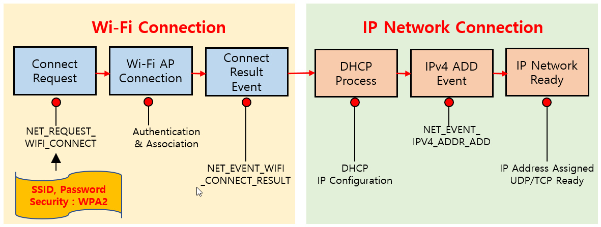
The overall process can be divided into two main stages: Wi-Fi Connection and IP Network Connection.
First, in the Wi-Fi Connection stage, an AP connection is requested using NET_REQUEST_WIFI_CONNECT with the SSID, password, and security information. Authentication and association then take place between the ESP32 and the AP, and the result is delivered to the application through the NET_EVENT_WIFI_CONNECT_RESULT event.
Once this process succeeds, the ESP32 is wirelessly connected to the Wi-Fi AP.
However, being connected to a Wi-Fi AP does not necessarily mean that the ESP32 is ready to use the IP network.
To perform IP-based communication such as UDP or TCP, the ESP32 needs an IP address. Therefore, after the Wi-Fi connection is established, the DHCP process is used to configure the IP network.
When an IPv4 address is assigned through DHCP, Zephyr generates the NET_EVENT_IPV4_ADDR_ADD event. When this event is received, we can confirm that the ESP32 has successfully obtained an IP address and is ready to communicate with other devices on the network.
Therefore, the overall process that we will verify in this exercise can be summarized as follows:
SSID / Password / Security Configuration → AP Connection Request → Authentication & Association → Wi-Fi Connection Complete → DHCP → IP Address Assignment → Network Ready
Once this process is complete, we can proceed to the next step and use UDP or TCP to exchange actual data between the ESP32 and other devices on the network.
Project Creation and Configuration
This exercise is based on the ESP32 project used in the previous Wi-Fi Scan exercise.
Since the Wi-Fi Scan project already contains the basic project structure and configuration required to use Wi-Fi on the ESP32, we will copy the existing skpang_esp32_can_wifiscan folder and create a new skpang_esp32_can_wificonnect project.
The folder structure of the newly created project is shown below.
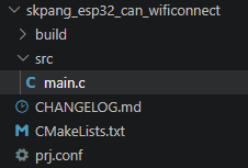
The basic project structure is the same as in the previous Wi-Fi Scan exercise. However, this time we need to connect to an AP and obtain an IP address through DHCP, so some project settings and source code need to be modified.
After creating the new project, we will check and modify the following files in order:
CMakeLists.txtprj.confCHANGELOG.md
After that, we will rewrite main.c to implement the Wi-Fi AP connection process.
Modifying CMakeLists.txt
For CMakeLists.txt, we will keep the configuration from the previous Wi-Fi Scan project and only change the project name to skpang_esp32_can_wificonnect, as shown below.
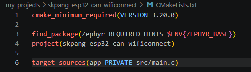
As before, target_sources() specifies src/main.c as the application source file. Since no additional source files are required in this exercise, no other settings need to be changed.
Modifying prj.conf
For prj.conf, we will keep most of the settings from the previous Wi-Fi Scan project and add the following two options.
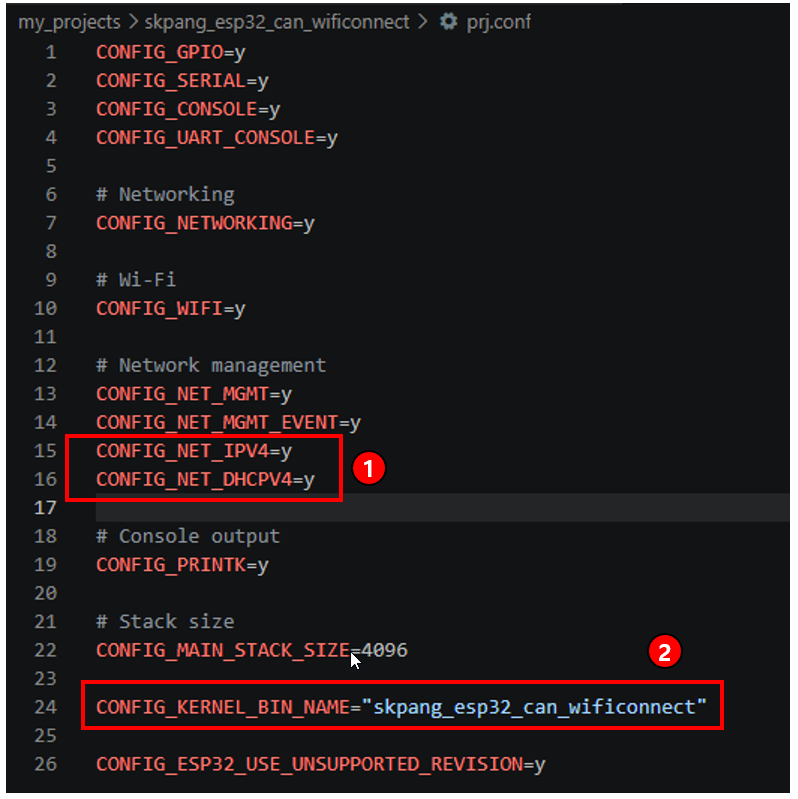
① Adding IPv4 and DHCP Configuration
In this exercise, the ESP32 needs to obtain an IP address through DHCP after connecting to the AP, so the following settings are added:
CONFIG_NET_IPV4 enables Zephyr’s IPv4 functionality, while CONFIG_NET_DHCPV4 enables the DHCP client functionality.
With these settings, the ESP32 can automatically obtain an IPv4 address through DHCP after connecting to the Wi-Fi AP.
② Changing the Kernel Binary Name
To match the new project name, we will also change the kernel binary name as follows:
With this setting, the name of the binary file generated during the build process is also changed to match the new project name.
The remaining Wi-Fi, Network Management, and console-related settings are kept the same as those used in the previous Wi-Fi Scan project.
Updating CHANGELOG.md
For CHANGELOG.md, we will complete the file by adding the changes made to the existing version.
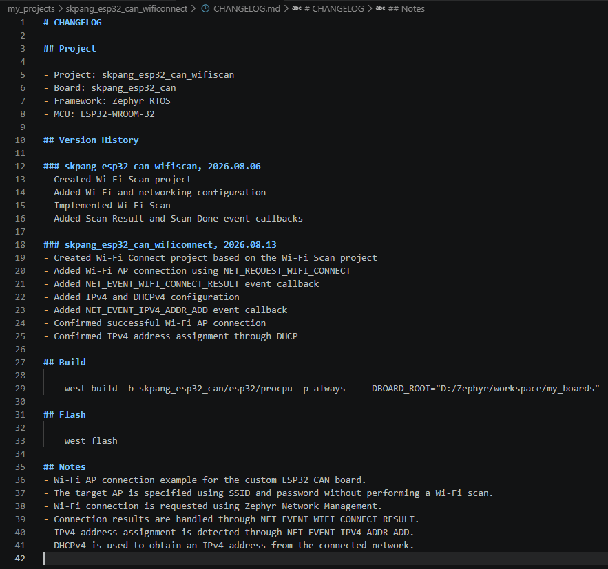
The file shown above is the completed version after finishing this exercise. When starting a project, there is no need to write down the implementation details in advance. Instead, changes and additions can be recorded sequentially as development progresses.
One particularly important item to record when creating the file is the Build command.
As the program is modified and tested repeatedly, the same Build command is used again and again. In particular, when using a Custom Board, the BOARD_ROOT path must be included, which makes the command longer and increases the chance of typing errors when entering it manually each time.
Therefore, it is convenient to record the Build command used for the project in CHANGELOG.md in advance and copy it whenever needed.
The Build command used in this project is as follows:
west build -b skpang_esp32_can/esp32/procpu -p always — -DBOARD_ROOT=”D:/Zephyr/workspace/my_boards”
By keeping the Build and Flash commands together with the major changes made during development, it becomes much easier to quickly identify the development environment and previous work when reopening the project later.
Program Implementation
This program implements the Wi-Fi AP connection process described earlier.
The overall program flow is as follows:
Check Network Interface → Register Event Callbacks → Configure Wi-Fi Connection Information → Request AP Connection → Handle Wi-Fi Connection Result → Handle IPv4 Address Event
In the program, the Wi-Fi connection result and IPv4 address assignment are handled through separate event callbacks.
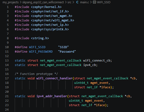
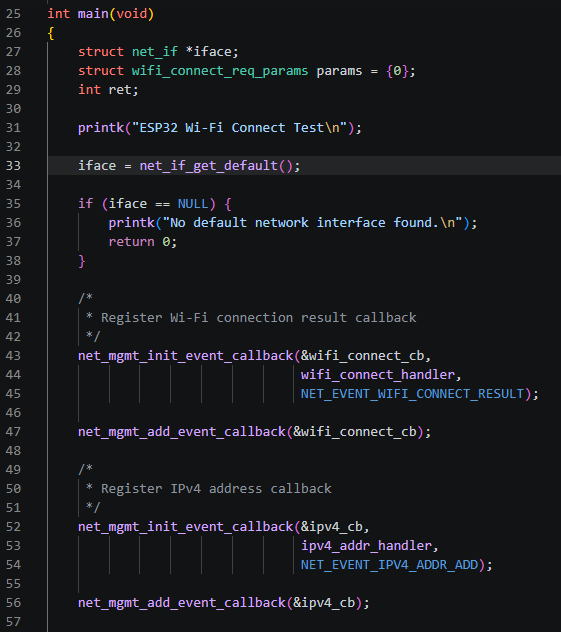
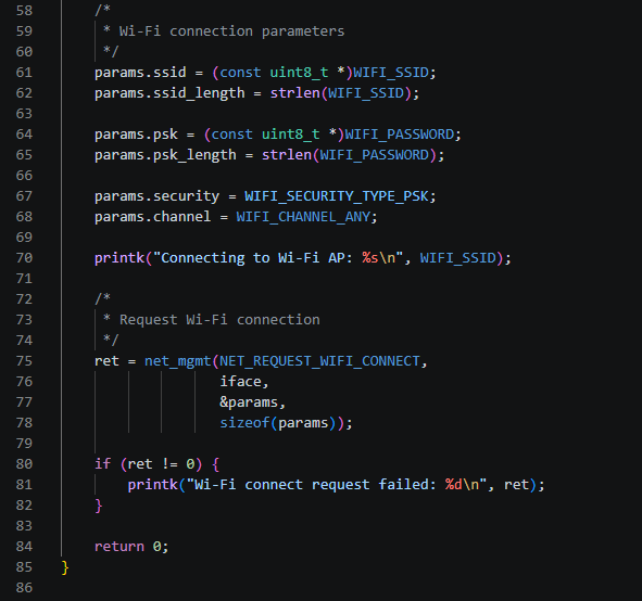
The complete main.c program is shown below.
Defining Wi-Fi Connection Information
First, define the SSID and password of the AP to connect to.
#define WIFI_SSID        "SSID"
#define WIFI_PASSWORD    "Password"
When actually using the program, replace "SSID" and "Password" with the connection information of the Wi-Fi AP you want to use.
In this exercise, we will connect to an AP using WPA2 security, so the security type will be configured later in the wifi_connect_req_params structure.
Preparing Event Callbacks
To handle the Wi-Fi connection result and IPv4 address assignment events, declare two callback structures.
static struct net_mgmt_event_callback wifi_connect_cb;
static struct net_mgmt_event_callback ipv4_cb;
wifi_connect_cb handles the result of the Wi-Fi AP connection, while ipv4_cb is used when an IPv4 address is assigned through DHCP.
The callback functions are also declared in advance.
static void wifi_connect_handler(struct net_mgmt_event_callback *cb,
                                 uint64_t mgmt_event,
                                 struct net_if *iface);

static void ipv4_addr_handler(struct net_mgmt_event_callback *cb,
                              uint64_t mgmt_event,
                              struct net_if *iface);
Getting the Network Interface
In main(), we first obtain the default Network Interface.
iface = net_if_get_default();net_if_get_default() returns a pointer to the Network Interface that is used as the default interface in the current system.
In this ESP32 Wi-Fi project, this interface is used to request a Wi-Fi connection and to handle subsequent IP network operations.
If no default Network Interface is available, the program terminates.
if (iface == NULL) {
    printk("No default network interface found.\n");
    return 0;
}
Registering the Wi-Fi Connection Event Callback
To receive the Wi-Fi connection result, register a callback for the NET_EVENT_WIFI_CONNECT_RESULT event.
net_mgmt_init_event_callback(&wifi_connect_cb,
                             wifi_connect_handler,
                             NET_EVENT_WIFI_CONNECT_RESULT);

net_mgmt_add_event_callback(&wifi_connect_cb);
net_mgmt_init_event_callback() specifies which event the callback will handle and which handler function will be called. Then, net_mgmt_add_event_callback() registers the callback with Zephyr’s Network Management event callback list.
When the AP connection result is generated, Zephyr calls wifi_connect_handler().
Registering the IPv4 Address Event Callback
Next, register a callback to check whether an IPv4 address has been assigned through DHCP.
net_mgmt_init_event_callback(&ipv4_cb,
                             ipv4_addr_handler,
                             NET_EVENT_IPV4_ADDR_ADD);

net_mgmt_add_event_callback(&ipv4_cb);
When an IPv4 address is added to the Network Interface, the NET_EVENT_IPV4_ADDR_ADD event is generated, and ipv4_addr_handler() is called.
This corresponds to the IP Network Connection stage described earlier.
Configuring Wi-Fi Connection Parameters
The information required for the Wi-Fi connection is configured in the wifi_connect_req_params structure.
struct wifi_connect_req_params params = {0};Set the SSID and password as follows:
params.ssid = (const uint8_t *)WIFI_SSID;
params.ssid_length = strlen(WIFI_SSID);

params.psk = (const uint8_t *)WIFI_PASSWORD;
params.psk_length = strlen(WIFI_PASSWORD);
The security type and channel are also configured.
params.security = WIFI_SECURITY_TYPE_PSK;
params.channel = WIFI_CHANNEL_ANY;
By using WIFI_CHANNEL_ANY, there is no need to specify a particular channel manually. The Wi-Fi driver can find the channel used by the AP and connect to it automatically.
Requesting a Wi-Fi AP Connection
Once all connection parameters are ready, request a connection to the AP using net_mgmt().
ret = net_mgmt(NET_REQUEST_WIFI_CONNECT,
iface,
¶ms,
sizeof(params));Here, NET_REQUEST_WIFI_CONNECT corresponds to the Connect Request shown in the diagram earlier.
The return value of net_mgmt() does not indicate whether the Wi-Fi connection itself has ultimately succeeded. It indicates whether the connection request was successfully accepted.
if (ret != 0) {
    printk("Wi-Fi connect request failed: %d\n", ret);
}
The actual Wi-Fi connection result is checked later through the NET_EVENT_WIFI_CONNECT_RESULT event.
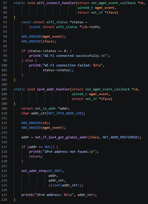
Checking the Wi-Fi Connection Result
When the Wi-Fi connection process is completed, the following handler is called.
static void wifi_connect_handler(struct net_mgmt_event_callback *cb,
                                 uint64_t mgmt_event,
                                 struct net_if *iface)
The Wi-Fi connection result is passed through the callback’s info field.
const struct wifi_status *status =
    (const struct wifi_status *)cb->info;
If status->status is 0, the AP connection was successful.
if (status->status == 0) {
    printk("Wi-Fi connected successfully.\n");
} else {
    printk("Wi-Fi connection failed: %d\n",
           status->status);
}
At this point, the wireless connection between the ESP32 and the Wi-Fi AP has been established.
After the Wi-Fi connection is established, ipv4_addr_handler() is called when an IPv4 address is assigned through DHCP.
First, obtain the currently available IPv4 address from the Network Interface.
addr = net_if_ipv4_get_global_addr(iface, NET_ADDR_PREFERRED);If the address is available, use net_addr_ntop() to convert it into a human-readable string.
net_addr_ntop(AF_INET,
              addr,
              addr_str,
              sizeof(addr_str));
Finally, print the assigned IPv4 address to the console.
printk("IPv4 address: %s\n", addr_str);When this message is displayed, we can confirm that the ESP32 has successfully obtained an IP address through DHCP.
The actual program flow can therefore be summarized as follows:
NET_REQUEST_WIFI_CONNECT → NET_EVENT_WIFI_CONNECT_RESULT → DHCP → NET_EVENT_IPV4_ADDR_ADD → IPv4 Address Confirmed
Once this process is complete, the ESP32 is ready to participate in the IP network, and we can proceed to actual data communication using UDP or TCP.
Build and Execution Results
Now, we will build the project and run it on the ESP32.
In the terminal, move to the project directory and run the Build command that was previously recorded in CHANGELOG.md.
If the build completes successfully, the memory usage for each region is displayed, followed by the message:
Successfully created ESP32 image.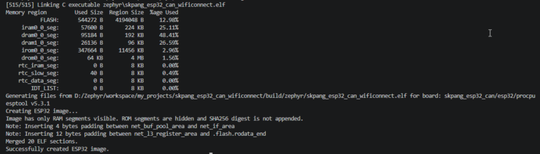
From the result above, we can confirm that skpang_esp32_can_wificonnect.elf was successfully generated and that an image that can be flashed to the ESP32 was created.
Next, flash the generated firmware to the ESP32.
The command is west flash.
west flashWhen this command is executed, Zephyr’s ESP32 runner uses esptool to detect the ESP32 and flash the firmware.
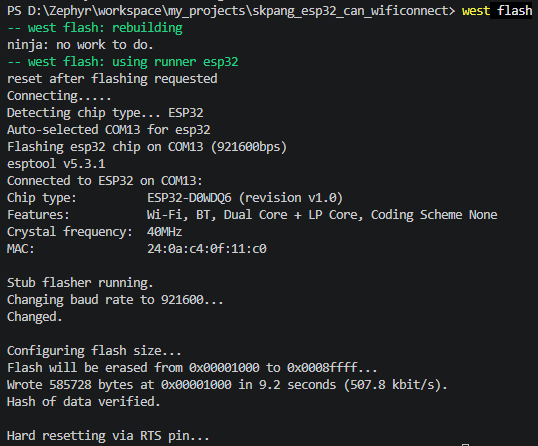
From the output above, we can see that the ESP32 was successfully detected through COM13 and that the firmware was written to Flash memory.
In particular, the following messages confirm that the flashing process was completed successfully:
Hash of data verified.

Hard resetting via RTS pin...
Once flashing is complete, the ESP32 resets and starts running the newly flashed firmware.
Now, open a Serial Terminal to check the Wi-Fi AP connection process and the IP address assignment result.
The screen below shows the Docklight Serial Terminal program.

From the execution result, we can see the following message:
Wi-Fi connected successfully.This message indicates that the ESP32 has successfully connected to the specified Wi-Fi AP.
The assigned IPv4 address is also displayed as follows:
IPv4 address: 192.168.0.8This indicates that an IPv4 address was successfully assigned to the ESP32 through DHCP after the AP connection was established.
Therefore, we can confirm that both stages discussed earlier—Wi-Fi Connection and IP Network Connection—were completed successfully.
In other words, the ESP32 is now connected to the Wi-Fi AP and has become a Network Device with its own IP address, ready to perform IP-based communication using protocols such as UDP and TCP.
Conclusion
In this exercise, we used Zephyr to connect the ESP32 to a Wi-Fi AP and verified the process of obtaining an IPv4 address through DHCP.
While the previous Wi-Fi Scan exercise focused on discovering information about nearby APs, this exercise went one step further by allowing the ESP32 to actually join a Wi-Fi network.
In particular, we confirmed that the Wi-Fi AP connection process and the IP address assignment process are separate stages, and that Zephyr can handle the result of each stage through Network Management events.
The ESP32 is now basically ready to use the IP network. However, we have not yet exchanged actual data between the ESP32 and another device.
In the next exercise, we will use UDP or TCP to send and receive actual data between the ESP32 and a PC. Through this, we will take the next step beyond Wi-Fi connectivity and examine how actual network communication works.