Introduction
STM32 microcontrollers are widely used in control boards for industrial equipment. In relatively simple systems, an STM32 can be connected directly to a touch screen to build an HMI. In higher-level networked or more complex processes, however, a Raspberry Pi or another SBC (Single Board Computer) may be used to handle data processing and communication.
In such systems, the STM32 and the host computer may need to exchange not only commands and device status information but also relatively large amounts of data such as configuration data and production information. Serial communication such as RS-232C is simple to implement, but it has limitations in terms of speed and scalability when the amount of data increases or faster communication is required.
In actual equipment, I had also felt the need to improve the communication speed with the HMI. Therefore, I wanted to directly verify how effectively data could be transferred by using the Ethernet capability of an STM32 rather than relying on RS-232C communication.
In the previous Wi-Fi tests, a router and DHCP were used as the test environment to verify network functionality. However, in actual industrial equipment, it is often preferable not to depend on an external network environment. The host computer and the STM32 control board should be able to communicate directly through an independent 1:1 network connection.
For this test, an SBC (Single Board Computer) and an STM32 board were connected directly with an Ethernet cable to establish a 1:1 Ethernet network, and 50 KB of data was transferred using TCP. The test also verified whether the data was received correctly and whether the STM32 could return the result as an ACK response.
The purpose of this test was not simply to transfer 50 KB of data. The main objective was to establish and verify the basic structure of Ethernet communication that can later be extended with Checksum or CRC-based data verification and application-specific protocols.
Overall System Configuration
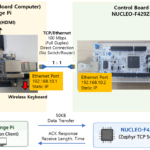
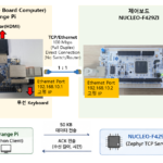
The figure below shows the overall system configuration.
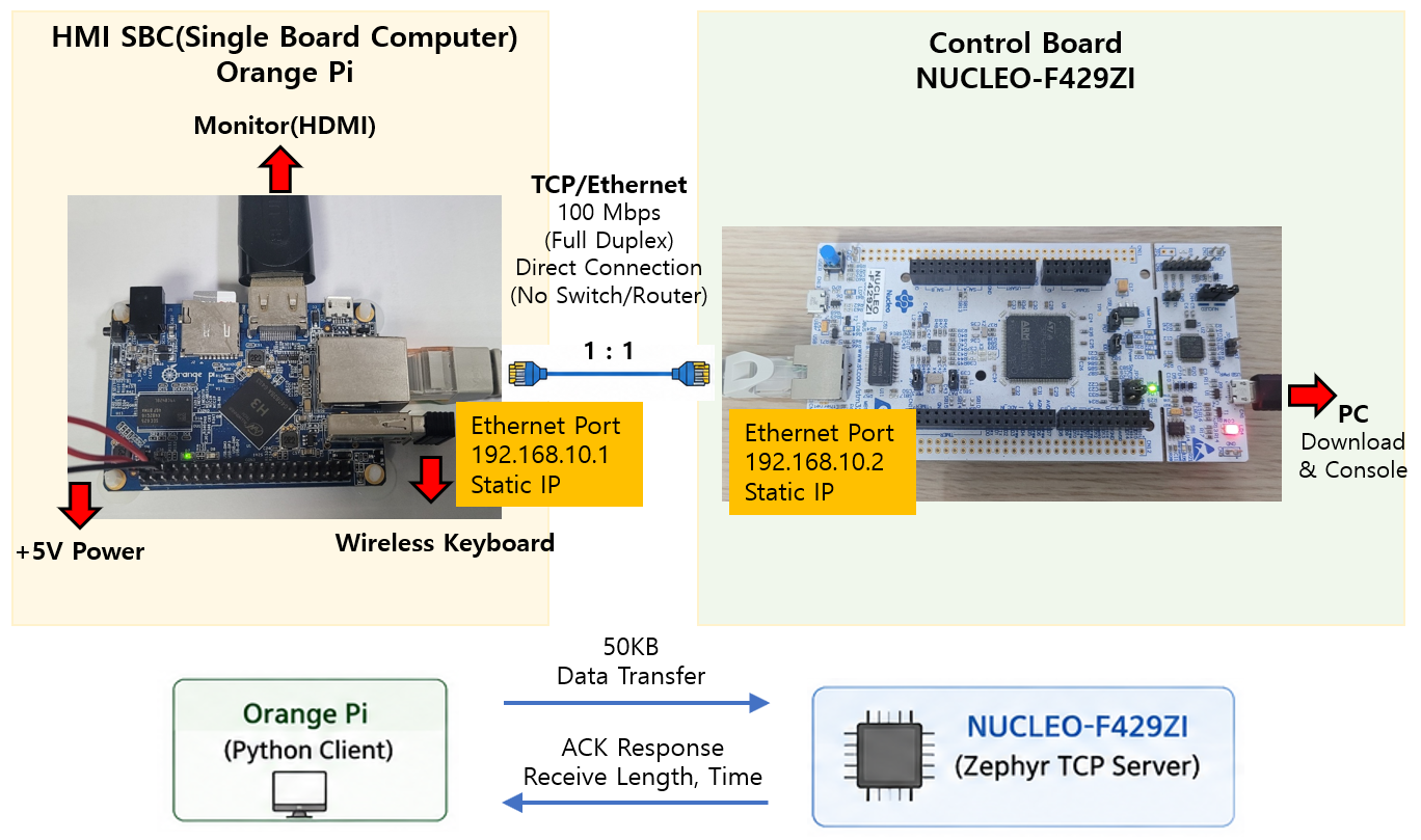
In this test, the Orange Pi and NUCLEO-F429ZI were connected directly with an Ethernet cable to establish a 1:1 Ethernet network. No separate switch or router was used. A static IP address of 192.168.10.1 was assigned to the Orange Pi, while 192.168.10.2 was assigned to the STM32.
The Orange Pi represents the host computer that would serve as the HMI in an actual system, and a Python program was used to verify TCP operation. The NUCLEO-F429ZI serves as the control board and operates as a TCP server based on Zephyr RTOS.
In this test, the Orange Pi sends 50 KB of data to the STM32. After receiving the data and verifying the payload, the STM32 returns an ACK to the Orange Pi containing the actual length of the received data and the time required to receive it.
The Orange Pi was used as the HMI SBC simply because it was the hardware currently available for this test, rather than for any specific technical reason. In an actual system, the same configuration can be implemented using a Raspberry Pi or another SBC with an Ethernet TCP/IP interface, without being limited to the Orange Pi.
50 KB Data Transfer and Verification
After completing the overall system configuration, 50 KB of data was transferred from the Orange Pi to the STM32 to verify that the data could be transmitted correctly.
The purpose of this test was not simply to confirm that a TCP connection could be established and data could be received. Instead, the goal was to verify the entire communication process as a single flow, as shown below.
Orange Pi Data Generation → TCP Transmission → STM32 Data Reception → Payload Verification → Reception Time Measurement → ACK Response → Result Verification on Orange Pi
Data Transfer Structure
The Python program running on the Orange Pi first generates the length of the data to be transmitted and a 50 KB payload, and then sends them to the STM32.
The STM32 receives the entire payload based on the specified data length and checks whether the actual amount of received data matches the expected length.
In this test, 50 KB = 51,200 bytes of data was used. A predefined test pattern was used for the payload so that the received data could be verified for correctness.
This makes it possible to verify not only that 51,200 bytes were received, but also that the contents of the received payload exactly match the data generated by the sender.
ACK Response and Result Verification
After the STM32 successfully completes the payload verification, it returns an ACK to the Orange Pi containing the following information:
- Actual length of the received data
- Data reception time measured by the STM32
The Orange Pi waits for the ACK after transmitting the data and then uses the returned information to confirm once again that the STM32 actually received and verified the data successfully.
In other words, this test does not end with one-way data transmission. Instead, it implements a complete communication flow:
Data Transmission → Reception Confirmation → Data Verification → Result Response
This provides a basic communication structure in which the sender can confirm the result of the data transfer.
Verification Results
The verification results are as follows.
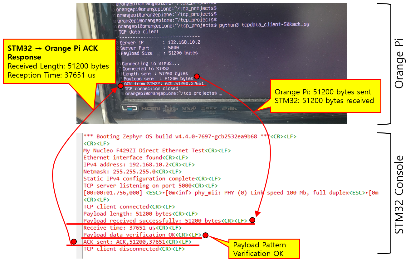
The figure above shows the actual result of the 50 KB data transfer test. The Python program running on the Orange Pi transmitted a 51,200-byte payload to the STM32. On the STM32 console, the message Payload received successfully: 51200 bytes confirms that the entire payload was received.
The test verified not only the size of the received data but also its contents. The STM32 checked the pattern of the received payload, and the message Payload data verification OK confirms that the transmitted data was received without corruption and the payload contents were correctly maintained.
The reception time measured by the STM32 was 37,651 µs. After completing the payload verification, the STM32 returned ACK,51200,37651 to the Orange Pi. The Orange Pi received the same ACK, allowing the sender to confirm that the STM32 successfully received and verified all 51,200 bytes of data.
Therefore, this test verified not only that a TCP connection could be established, but also the complete communication flow:
50 KB Data Transfer → Received Length Verification → Payload Verification → Reception Time Measurement → ACK Response
This confirms that the basic communication structure operates correctly from data transmission through final result verification.
Communication Protocol Extension
In this test, the data length and payload were transmitted, and the STM32 returned an ACK after verifying both the length of the received data and the payload pattern.
For this test, a predefined pattern was used to verify that the payload was transferred correctly. In an actual system, however, this method can be replaced with a Checksum or CRC to improve data integrity verification.
In addition, an actual system may require information such as commands, data types, and status information as well as the data length. This information can be added to a header to extend the communication structure into a custom protocol, as shown below.
+----------+-------------+---------------+
|  Header  |   Payload   | Checksum/CRC  |
+----------+-------------+---------------+
               ↓
           ACK / NACK
The header can contain information such as Command, Data Type, and Data Length, while the ACK can include the processing result or an error code.
Therefore, the communication structure verified in this test—
Data Transfer → Payload Verification → ACK Response
—is not limited to transferring 50 KB of data. It can serve as a basic communication framework for developing application-specific protocols for actual equipment in the future.
Example Project Download and Usage
This article focuses on the overall Ethernet communication structure and the results of the 50 KB data transfer and verification test, rather than providing a detailed explanation of the source code itself.
To allow you to test the same configuration directly or examine the implementation in more detail, the Zephyr project and Python test program used in this test are provided together.
They can be downloaded from the link below.
The compressed file includes the NUCLEO-F429ZI board configuration and application project.
The project folder structure is as follows.
my_nucleo_f429zi_tcpdata-50kcack_R/
│
├── my_nucleo_f429zi/                 # Board Configuration
│
└── my_nucleo_f429zi_tcpdata-50kcack/ # Application Project
    └── tools/                         # Python Test Program
First, build the application in the Zephyr environment and flash it to the NUCLEO-F429ZI. For the board configuration, use the included my_nucleo_f429zi folder.
The Orange Pi and STM32 Ethernet IP addresses are configured as follows.
Orange Pi : 192.168.10.1
STM32     : 192.168.10.2
TCP Port : 5000tools folder on the Orange Pi.python3 tcpdata_client-50kack.py50 KB Data Transfer → STM32 Payload Verification → ACK Response
Note: When using the project in a different network environment, the IP address and port settings in both the STM32 and Python programs must be modified accordingly.
Conclusion
In this test, the Orange Pi and NUCLEO-F429ZI were connected directly with an Ethernet cable to establish a 1:1 Ethernet network, and 50 KB of data was transferred and verified using the TCP/IP functionality of Zephyr RTOS.
The STM32 successfully received the 51,200 bytes transmitted from the Orange Pi, and payload pattern verification confirmed that the data contents were transferred correctly. The STM32 also measured the reception time and returned the result to the Orange Pi through an ACK. This confirmed that the entire communication process—from data transmission to verification and response—operated correctly.
The role of Zephyr RTOS was also important in this process.
Implementing Ethernet communication directly on an STM32 requires consideration of many components, including the Ethernet driver, TCP/IP network stack, sockets, and their integration with the application. Zephyr provides these components as part of its networking environment, allowing them to be used together. Further details can be found in the official Zephyr documentation for Ethernet and BSD Sockets.
This allowed the test to focus more on designing the data communication structure and application protocol required for actual equipment, rather than on the low-level implementation details of the hardware and network stack.
The significance of this test is not simply that the STM32 was able to receive 50 KB of data. More importantly, it established a basic communication structure for transmitting, receiving, verifying, and responding to data over Ethernet between a host computer and an STM32 control board.
In the future, the payload pattern verification can be replaced with Checksum or CRC-based verification, and information such as Command, Data Type, and Data Length can be defined in the header. Based on the system developed in this test, it should therefore be possible to extend the communication structure into a custom Ethernet communication protocol suitable for actual equipment.