Introduction
This article is the fifth part of the Zephyr ESP32 series and covers TCP communication. TCP/IP is one of the most widely used communication methods in computer networks.
In the previous UDP communication project, we verified basic network communication by exchanging data between the ESP32 and a PC. This time, we will use TCP to establish a connection between the ESP32 and the PC and exchange data in both directions.
The goal of this project is to connect the ESP32 to a Wi-Fi network, configure it to operate as a TCP client, and communicate with a TCP server running on the PC.
What Is TCP Communication?
TCP (Transmission Control Protocol) is a Protocol for reliably exchanging data between two devices connected to a network.
In the previous project, UDP transmitted data without establishing a connection with the other device in advance. Its structure is simple and data can be transmitted quickly, but it does not guarantee whether the data has actually reached the destination or whether it has arrived in the correct order.
TCP, on the other hand, first establishes a Connection with the other device before transmitting data.
Once the connection has been established, data can be exchanged while checking whether it has been delivered correctly. If data is lost during transmission, it can be retransmitted, and when multiple pieces of data are transmitted, TCP ensures that they are delivered in the original order.
The main characteristics of TCP are as follows.
- Connection-oriented
A Connection is established with the other device before data transmission. - Reliable transmission
TCP checks whether data has been delivered correctly and retransmits it if necessary. - Ordered delivery
Data is delivered in the same order in which it was transmitted. - Bidirectional communication
Once a Connection is established, both sides can transmit and receive data.
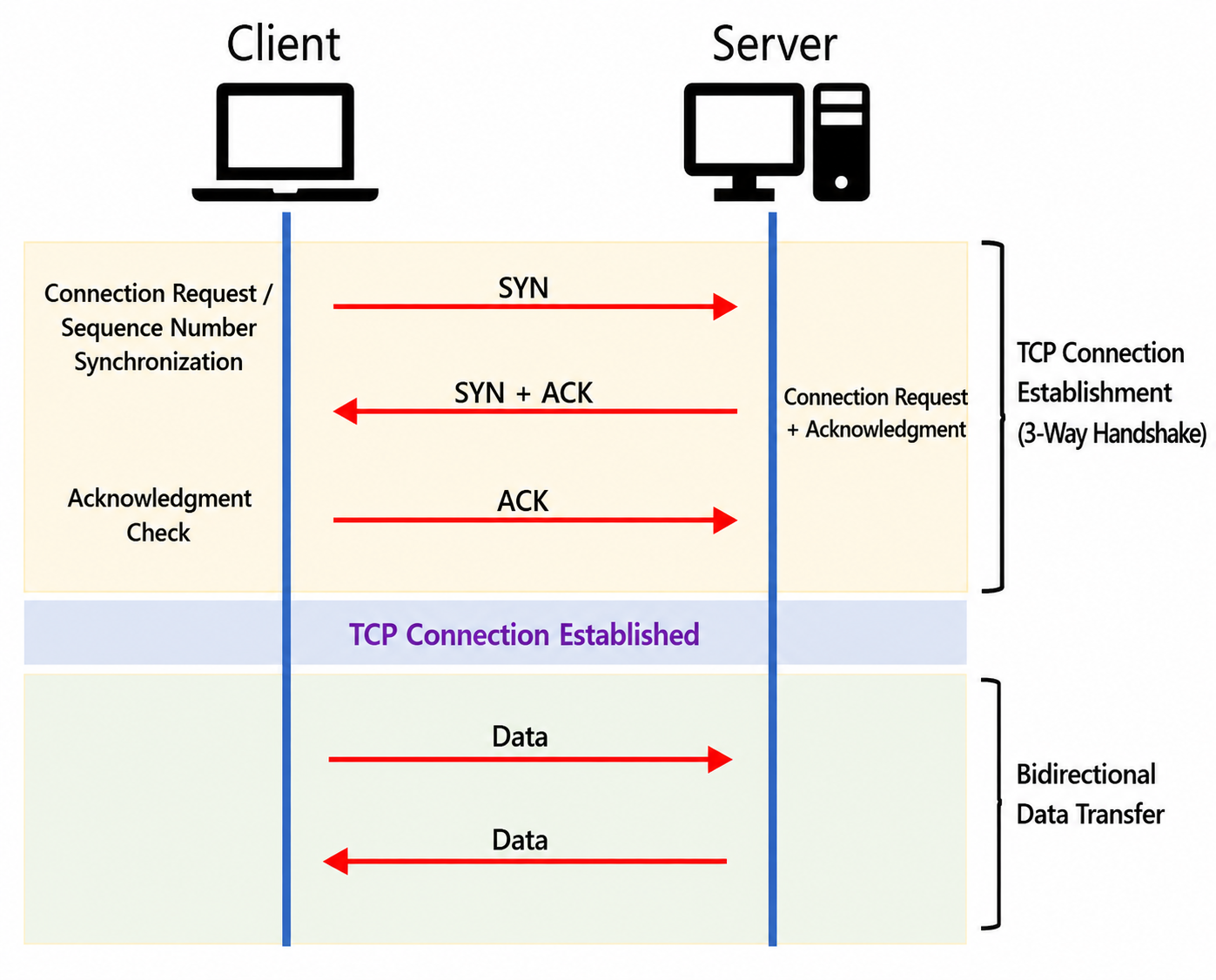
When establishing a TCP Connection, a process known as the 3-Way Handshake is generally used.
The Client sends a SYN to request a connection, the Server responds with SYN + ACK, and the Client sends an ACK in return. The TCP Connection is then established.
Here, SYN (Synchronize) is a control Flag used to synchronize the Sequence Numbers used for data transmission when starting a TCP Connection. It indicates the beginning of a TCP connection request.
The following figure illustrates the TCP communication process.
Project Architecture
In this project, the ESP32 operates as a TCP Client, while the PC operates as a TCP Server. The ESP32 and PC are connected through a Wi-Fi Network, and the ESP32 connects to the Server using the PC’s IP Address and TCP Port.
The following figure shows how the TCP Connection process described above is implemented in this project using Zephyr and Python.
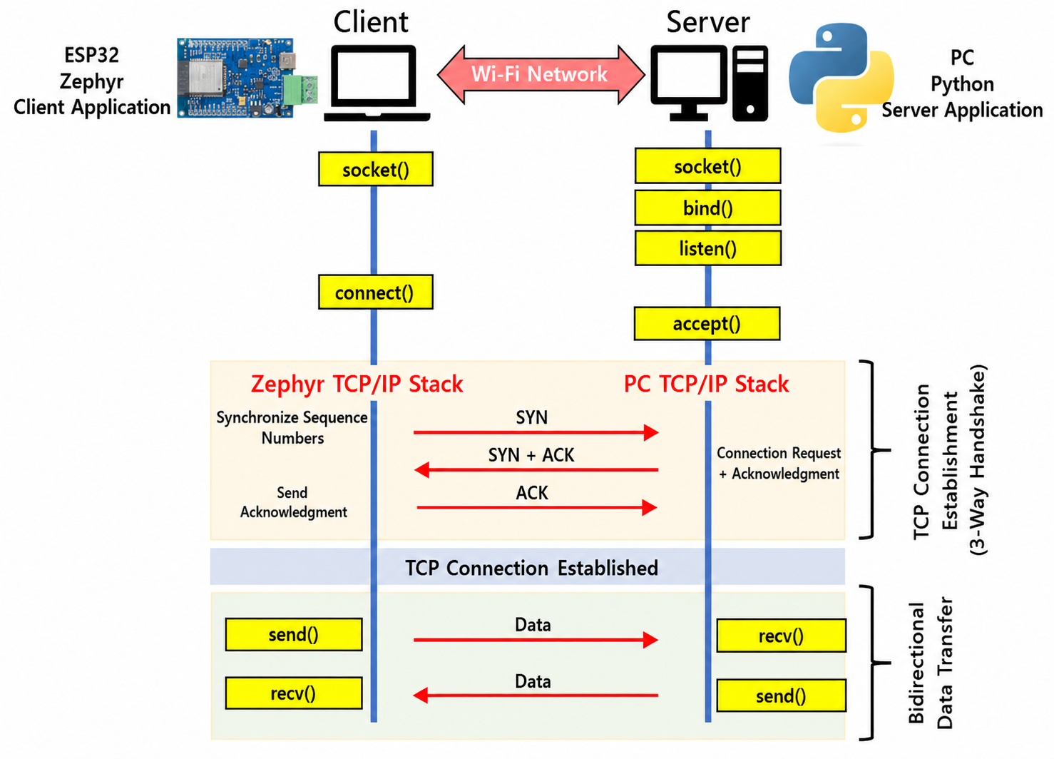
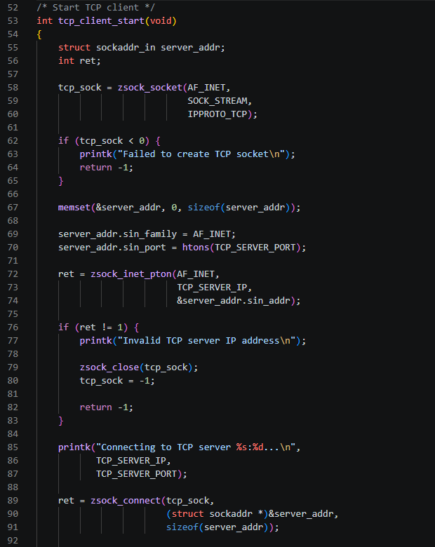
In the ESP32 Application, a TCP Socket is created using Zephyr’s Socket API, and connect() is called.
The 3-Way Handshake is then performed between the Zephyr TCP/IP Network Stack and the PC’s TCP/IP Stack, establishing the TCP Connection.
On the PC, a TCP Server written in Python is executed. The Server waits for a Client connection on a specified Port, and when the ESP32 requests a connection, the Server accepts it and establishes the TCP Connection.
After the TCP Connection is established, the ESP32 exchanges data with the PC using send() and recv(). The PC Server can also use the same Connection to send data to the ESP32 or receive data transmitted from the ESP32.
The overall operation of this project is as follows.
- The ESP32 connects to the Wi-Fi AP and obtains an IP Address.
- The Python TCP Server is started on the PC and waits for a Client connection.
- The ESP32 creates a TCP Socket.
- The ESP32 calls
connect()to request a connection to the PC Server. - A 3-Way Handshake is performed between the Zephyr TCP/IP Network Stack and the PC’s TCP/IP Stack.
- The TCP Connection is established.
- The ESP32 and PC exchange data bidirectionally through the established Connection.
Once the TCP Connection is established, multiple data transfers can take place while maintaining a single connection. In this project, the ESP32 transmission and reception operations are handled in separate Threads so that they do not interfere with each other.
Therefore, the general TCP structure described in the previous section as Client → Connection Establishment → Bidirectional Data Transfer is implemented in this project as ESP32/Zephyr → TCP Connection → PC/Python Server.
For more information about the BSD Socket API and TCP/IP Network Programming provided by Zephyr, refer to the official documentation.
Zephyr Documentation – BSD Sockets
Creating the Project and Configuring Files
This TCP communication project is created based on the Wi-Fi UDP project used in the previous exercise.
First, copy the existing skpang_esp32_can_wifiudp project and rename it as follows.
skpang_esp32_can_wifitcp
The process of connecting to a Wi-Fi AP and obtaining an IP Address using DHCP is the same as in the UDP project. Therefore, the existing project configuration is retained, while the UDP transmission and reception components are replaced with TCP Client communication.
The project is organized as follows.
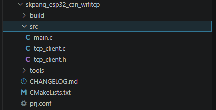
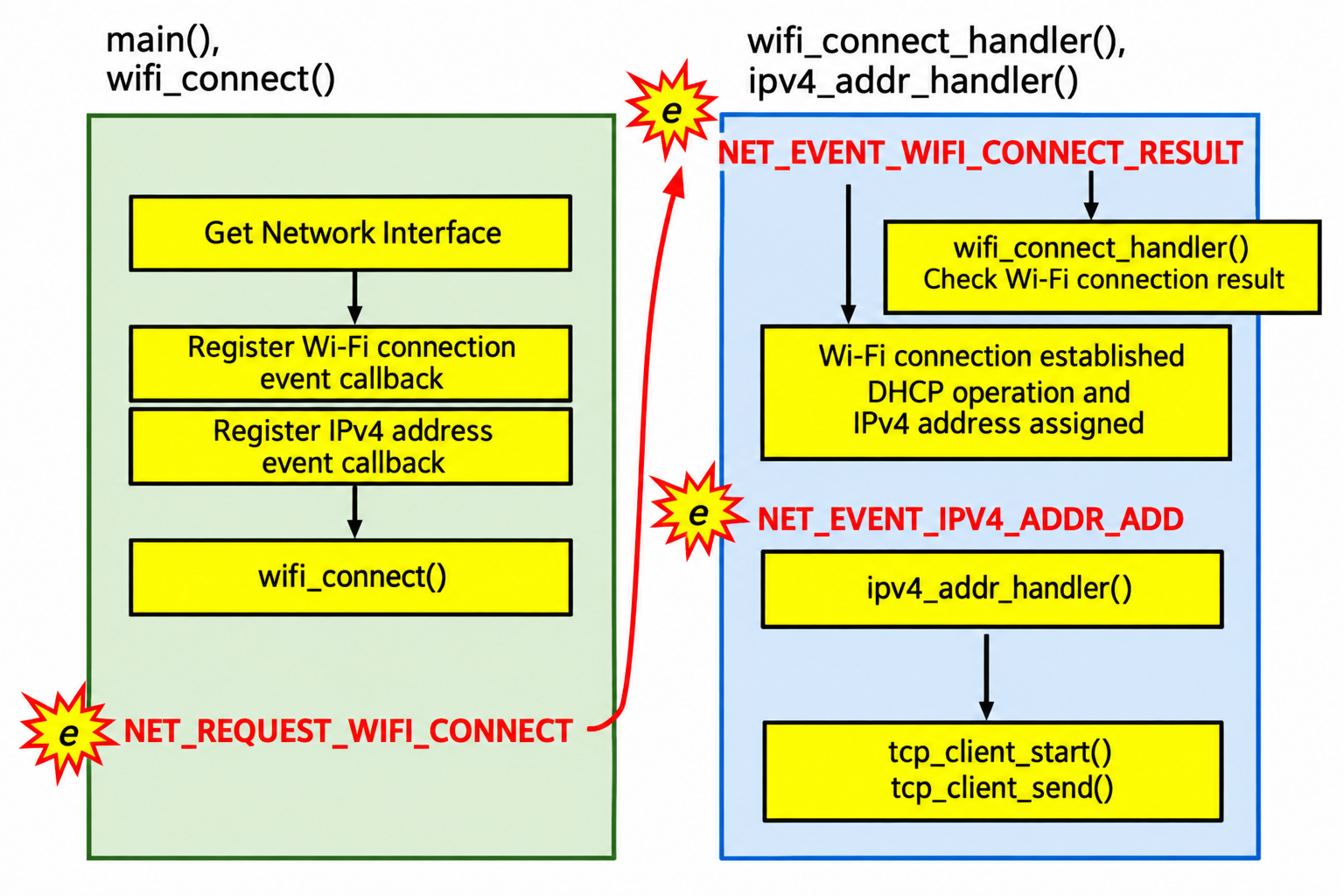
In main.c, the Wi-Fi AP connection and IP Address assignment are handled first. Once the Network is ready, the TCP Client is started.
The TCP communication functions are separated into tcp_client.c and tcp_client.h. By placing TCP Socket creation, Server connection, and data transmission/reception in separate files, main.c can be kept from becoming unnecessarily complex.
CMakeLists.txt
Add the Source File used to implement the TCP Client to CMakeLists.txt.
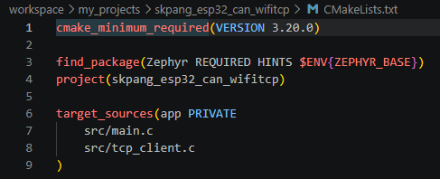
This allows main.c and tcp_client.c to be built together.
prj.conf
To use TCP communication, Zephyr’s Network and Socket features must be enabled.
The Wi-Fi, Network, IPv4, and DHCP settings used in the previous Wi-Fi AP connection project are retained. In this project, the TCP feature required for TCP Socket communication is additionally enabled.
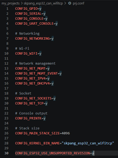
CONFIG_NETWORKING enables Zephyr’s Network functionality, while CONFIG_NET_IPV4 enables IPv4 support.
CONFIG_NET_TCP enables the TCP Protocol, and CONFIG_NET_SOCKETS allows the Application to use the Socket API.
Implementing the ESP32 TCP Client
This project is mainly organized around main.c and tcp_client.c.
main.c
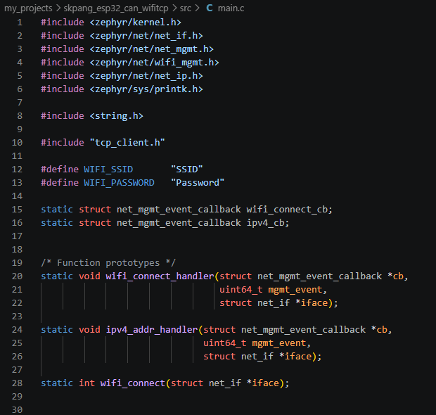
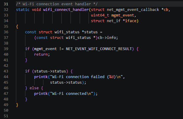
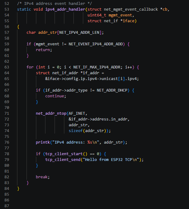
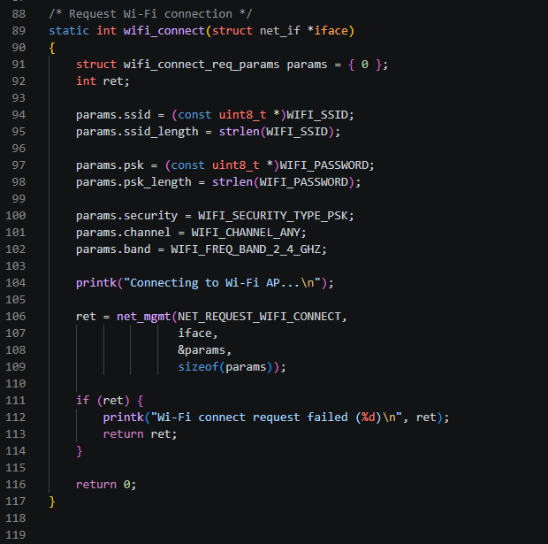
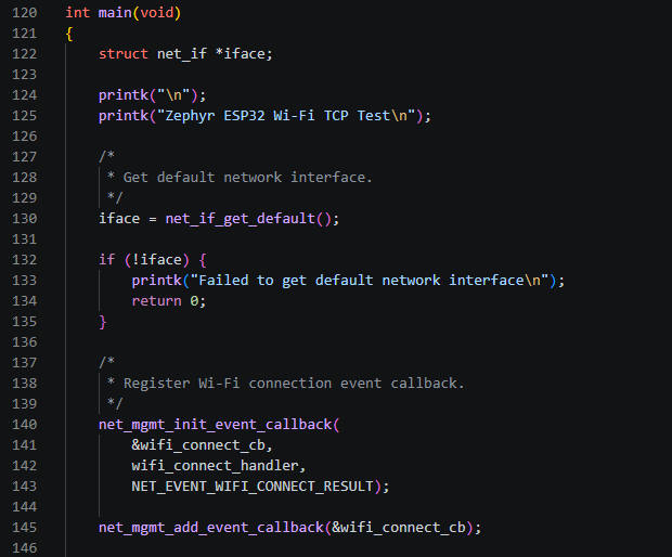
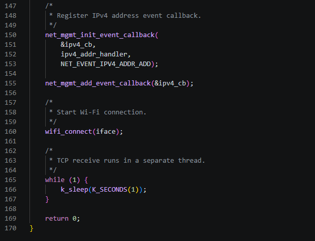
The Wi-Fi connection section of main.c has already been covered in detail in the previous project. However, in this TCP project, the TCP Client starts only after the Wi-Fi connection and IP Address assignment have been completed. Therefore, we will briefly review the overall operation once again.
TCP Transmission
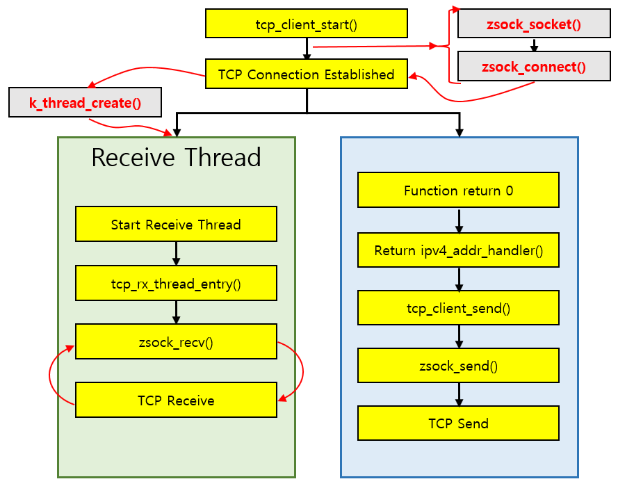
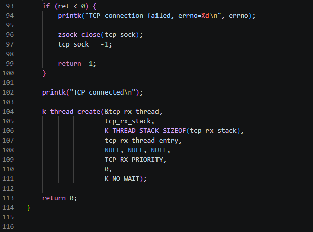
After creating the Receive Thread, the existing program execution flow continues.
When tcp_client_start() completes successfully, it returns 0, and the program returns to ipv4_addr_handler(), which originally called the function.
As shown earlier in main.c, the following code is then executed.
if (tcp_client_start() == 0) {
    tcp_client_send("Hello from ESP32 TCP\n");
}
Therefore, when tcp_client_start() succeeds, tcp_client_send() is called.
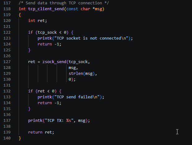
Inside tcp_client_send(), zsock_send() is used to transmit data to the PC TCP Server through the already established TCP Connection.
An important point in this structure is that the execution flows for TCP reception and transmission are separated.
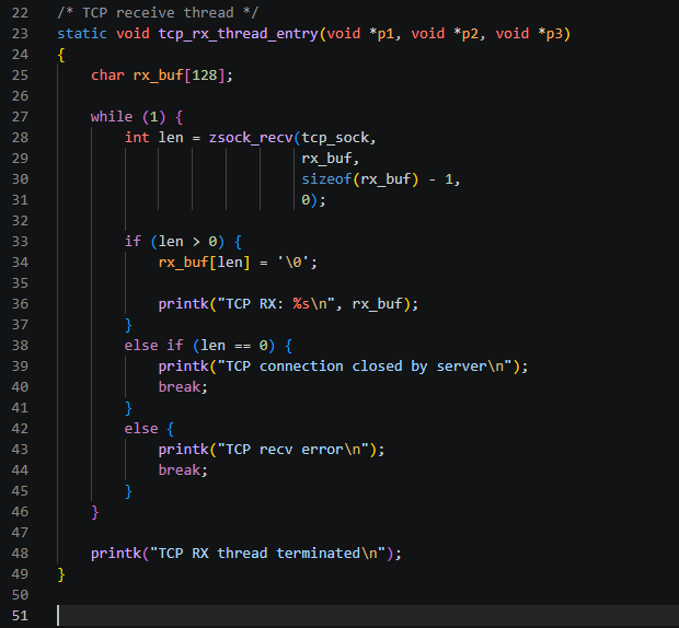
While the Receive Thread continuously waits for data from the PC using zsock_recv(), the existing program flow can transmit data using tcp_client_send().
Therefore, the overall flow after the TCP Connection is established can be summarized as follows.
Create TCP Socket → Connect to TCP Server → Create Receive Thread → Wait for Incoming Data
At the same time, the existing execution flow proceeds as follows.
tcp_client_start() completes → Return to ipv4_addr_handler() → tcp_client_send() → TCP Data Transmission
By using a separate Receive Thread in this way, the program can handle TCP transmission and reception without blocking other program operations while zsock_recv() waits for incoming data.
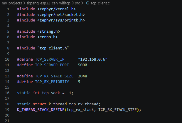
The complete tcp_client.c code is shown below.
Implementing the PC TCP Server
The PC TCP Server is implemented as a Python program.
Since the main focus of this project is to implement a TCP Client on the ESP32 using the Zephyr Socket API, we will only briefly examine the overall structure and operation of the Python code running on the PC TCP Server.
The PC Server waits for a connection from the ESP32 Client on TCP Port 5000. Once the connection is established, data can be exchanged bidirectionally with the ESP32.
To prevent data reception and keyboard input for transmission from interfering with each other, receive_thread() and send_thread() are executed as separate Threads. receive_thread() continuously receives data sent from the ESP32, while send_thread() sends Messages entered by the user to the ESP32.
The complete program is shown below.
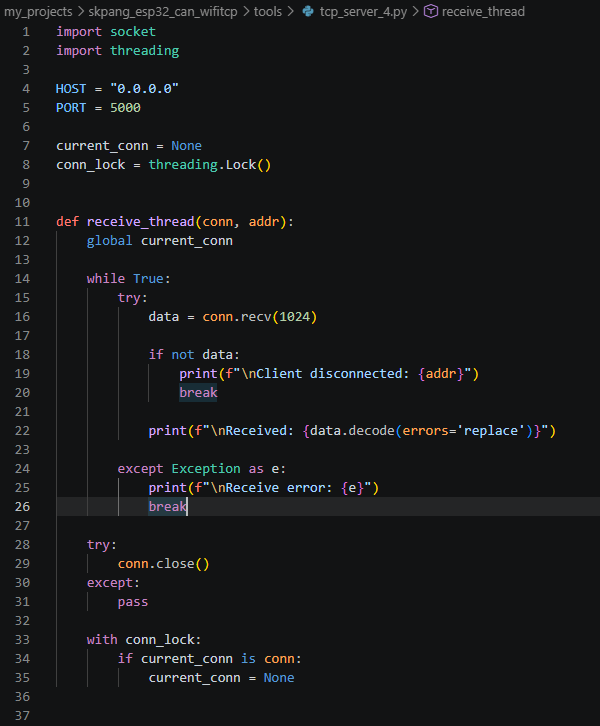
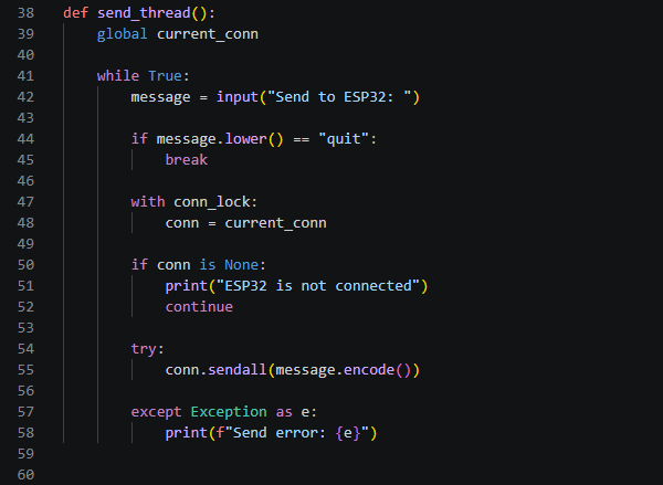
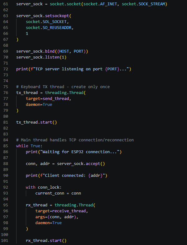
The basic operation flow of the code is as follows.
socket() → bind() → listen() → accept() → TCP Connection → Data Transmission/Reception
The Server creates a TCP Socket using socket() and binds it to Port 5000 using bind(). It then waits in the listen() state for a Client Connection. When the ESP32 requests a connection, accept() is used to establish the TCP Connection.
After the Connection is established, receive_thread() receives data transmitted from the ESP32, while send_thread() sends data entered by the user to the ESP32.
If the Connection with the ESP32 is lost, the Server returns to accept() and waits for a new Connection. Therefore, even if the ESP32 is reset or the TCP Connection is re-established, the Server can accept the new connection without restarting the Server program.
Build and Test
Now, let’s build the project and verify the actual TCP communication.
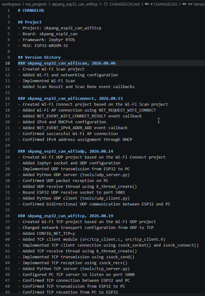
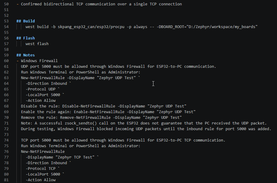
As with the previous projects, we will use the build commands recorded in CHANGELOG.md. Run the commands after moving the Terminal’s current Directory to the Project Directory.
The build command is as follows.
## Build
west build -b skpang_esp32_can/esp32/procpu -p always -- -DBOARD_ROOT="D:/Zephyr/workspace/my_boards"
After the build completes successfully, Flash the Firmware to the ESP32.
## Flash
west flash
Before running the ESP32, start the Python TCP Server created earlier on the PC.
python tools/tcp_server_4.pyThe PC TCP Server waits for a Connection from the ESP32 on Port 5000.
When the ESP32 starts, it first connects to the Wi-Fi AP and obtains an IPv4 Address through DHCP. It then calls tcp_client_start() to request a Connection to the PC TCP Server.
Once the TCP Connection is successfully established, the ESP32 operates in the following sequence.
Wi-Fi Connection → IPv4 Address Assignment → Connect to TCP Server → TCP Connection Established → Send Initial Message
On the PC Server, you can verify the "Hello from ESP32 TCP" Message sent by the ESP32.
After that, you can enter a Message on the PC and receive it through the ESP32’s Receive Thread. This confirms that bidirectional TCP communication between the PC and ESP32 is operating over a single TCP Connection.
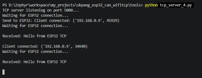
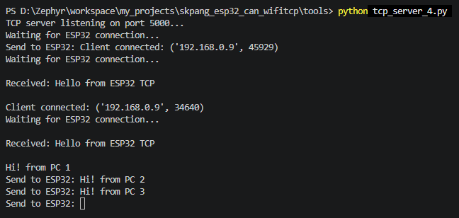
The following screen shows tcp_server_4.py running on the PC.
The following is the ESP32 Console screen viewed using Docklight.
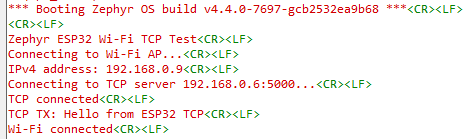
First, when tcp_server_4.py is started on the PC, the TCP Server waits for a connection from the ESP32 Client on Port 5000.
When the ESP32 starts, it connects to the Wi-Fi AP and obtains an IPv4 Address through DHCP. It then requests a TCP Connection to the PC TCP Server using the PC Server’s IP Address and Port 5000.
On the PC Server screen, you can confirm that the ESP32 Client has connected as follows.
Client connected: ('192.168.0.9', 45929)Here, 192.168.0.9 is the IPv4 Address assigned to the ESP32, and 45929 is the Source Port used by the ESP32 for this TCP Connection.
Once the TCP Connection is established, tcp_client_start() completes successfully, and tcp_client_send() is then executed to send the initial Message to the PC.
As a result, the following Message is received by the PC Server.
Received: Hello from ESP32 TCPThe same process can also be confirmed on the ESP32 Console.
Wi-Fi connected
IPv4 address: 192.168.0.9
Connecting to TCP server 192.168.0.6:5000...
TCP connected
TCP TX: Hello from ESP32 TCP
This output shows that the sequence of Wi-Fi Connection → IPv4 Address Assignment → PC TCP Server Connection → TCP Connection Establishment → Data Transmission from ESP32 to PC was completed successfully.
You can also see that the Source Port assigned to the ESP32 changed from 45929 to 34640 after the ESP32 was reset. When a new TCP Connection is created, the Client-side Source Port may change, while the Server continues to wait for connections on the fixed Port 5000.
From the results so far, we have confirmed that the ESP32 TCP Client successfully connects to the PC TCP Server and TCP data is transmitted from the ESP32 to the PC.
Next, we will send Messages from the PC Server and verify that zsock_recv() running in the ESP32’s separate Receive Thread receives the data correctly.
In the following test, the PC Server sends the Messages "Hi! from PC 1", "Hi! from PC 2", and "Hi! from PC 3".
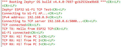
The following screen shows the data received by the ESP32.
Messages entered in the PC Server’s send_thread() are transmitted to the ESP32 through the already established TCP Connection.
On the ESP32, the separate Receive Thread created earlier executes zsock_recv() and waits for incoming data. When a Message is sent from the PC, zsock_recv() receives it and displays it on the Console.
On the ESP32 Console, you can confirm that all three Messages sent from the PC were received as follows.
TCP RX: Hi! from PC 1
TCP RX: Hi! from PC 2
TCP RX: Hi! from PC 3
Even after receiving one Message, the Receive Thread does not terminate. Instead, it calls zsock_recv() again and waits for the next Data. Therefore, even if multiple Messages are sent from the PC, the ESP32 can continue receiving them.
This confirms that, through a single TCP Connection, not only ESP32 → PC transmission but also PC → ESP32 reception operates correctly.
In other words, the bidirectional TCP communication between the ESP32 and PC, which was the goal of this project, has been successfully verified.
UDP vs. TCP
In both the previous UDP project and this TCP project, data was transmitted and received between the ESP32 and PC through a Wi-Fi Network.
With UDP, data can be transmitted immediately by specifying the destination IP Address and Port without establishing a separate Connection. With TCP, however, a Connection must first be established between the Client and Server before data can be transmitted or received.
In this project, the ESP32 established a Connection with the PC TCP Server using zsock_connect(), and then transmitted and received data using zsock_send() and zsock_recv().
The main differences between the two Protocols can be summarized as follows.
| Item | UDP | TCP |
|---|---|---|
| Communication method | Connectionless | Connection-oriented |
| Connection establishment | Not required | Required |
| Data format | Datagram | Byte Stream |
| Main send/receive API | sendto(), recvfrom() |
send(), recv() |
| Data delivery | Delivery and order not guaranteed | Reliable and ordered delivery |
| Communication structure | Relatively simple | Relatively complex |
| Communication overhead | Relatively low | Relatively high |
UDP has a simple structure and low Overhead, while TCP maintains a Connection and provides reliable, ordered data delivery.
Therefore, rather than asking which Protocol is better, it is important to choose UDP or TCP according to the communication requirements of the Application.
Through these two projects, we were able to examine the differences between UDP and TCP not only in theory, but also directly through the Socket API and the actual program structure.
Conclusion
In this project, we configured the ESP32 as a TCP Client and the PC as a TCP Server and verified bidirectional TCP communication over a Wi-Fi Network.
We examined the overall flow from Wi-Fi connection and IPv4 Address assignment to starting the TCP Client, and learned how to establish a TCP Connection using the Zephyr Socket API. We also confirmed how a separate Receive Thread can be used to handle data reception.
Through the previous UDP project and this TCP project, we were able to see how Network communication is implemented on the ESP32 and compare the differences between the two Protocols through actual programs.
In the next project, we will build on this Network communication and use the MQTT Protocol to exchange Messages between the ESP32 and an MQTT Broker.