Introduction
In the previous posts, I connected the STM32 and the PT100 analog interface board and tested two different methods of reading ADC values.
The first method was the simplest Polling method, where the ADC was read every 100ms and sampled 16 times to calculate an average.
This method has the advantage of being simple to implement, but because it is a blocking method, it can affect other processes running simultaneously.
The second method was Time-Distributed Sampling, where one sample was taken every 10ms and the average was calculated every 100ms.
This method distributes the sampling work over time, reducing the instantaneous CPU load. However, the CPU still has to directly read and process the ADC data.
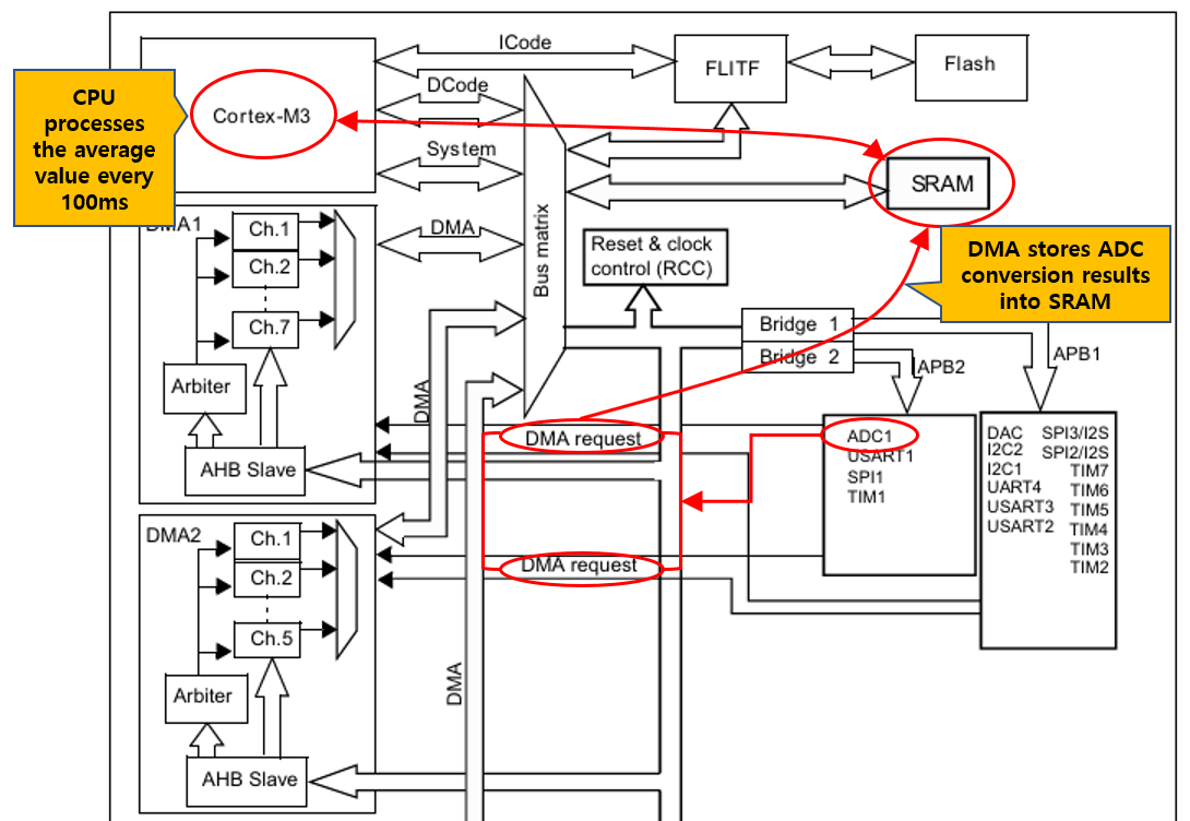
In this article, to minimize CPU involvement and implement a more efficient sampling structure, I applied the DMA (Direct Memory Access) based ADC sampling method.
For detailed information about the ADC of the STM32F103, please refer to the Reference Manual.
Below is the Reference Manual link.
Main Body
Experimental Setup
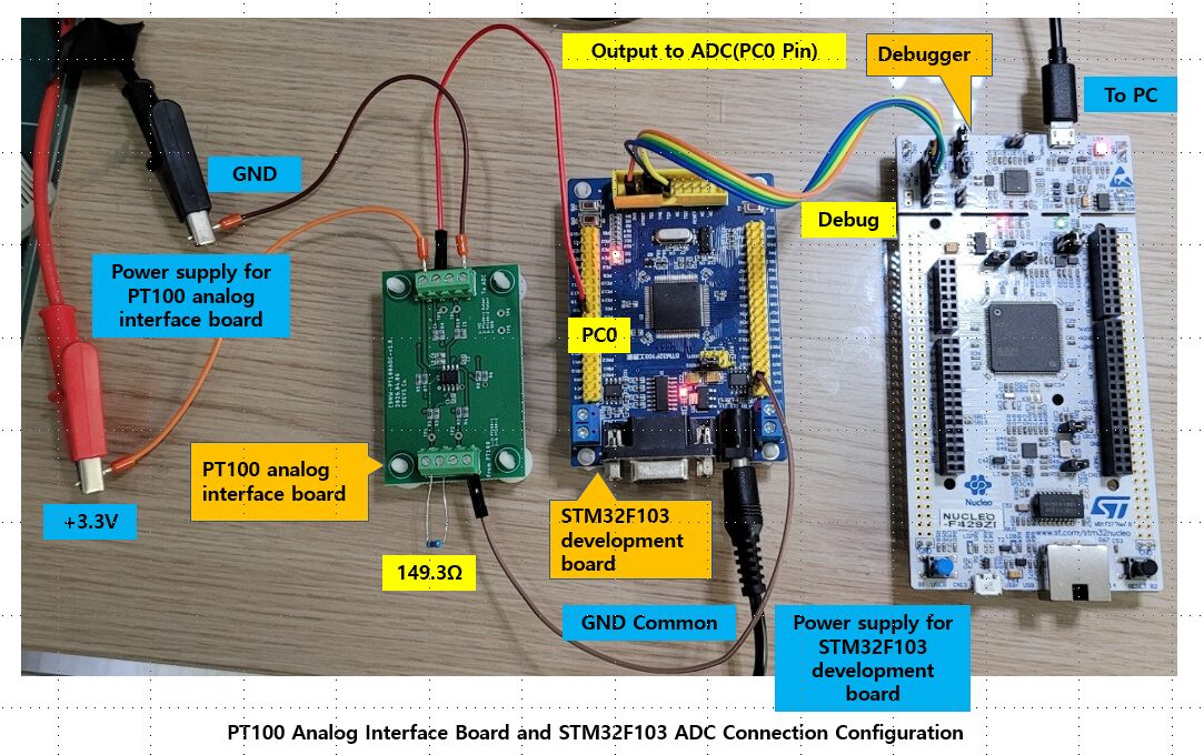
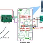
The hardware configuration used in this experiment is the same as in the previous two experiments.
Instead of an actual PT100 sensor, a precision resistor (149.3Ω) was connected to simulate resistance changes according to temperature, and the output voltage of the PT100 analog interface board was connected to the ADC input (PC0) of the STM32F103 development board.
The ADC DMA operation status and measurement results were verified using the debugger’s Live Expression feature.
ADC DMA Implementation
CubeMX ADC DMA 설정
To apply DMA to the ADC, additional ADC and DMA settings must be configured in CubeMX.
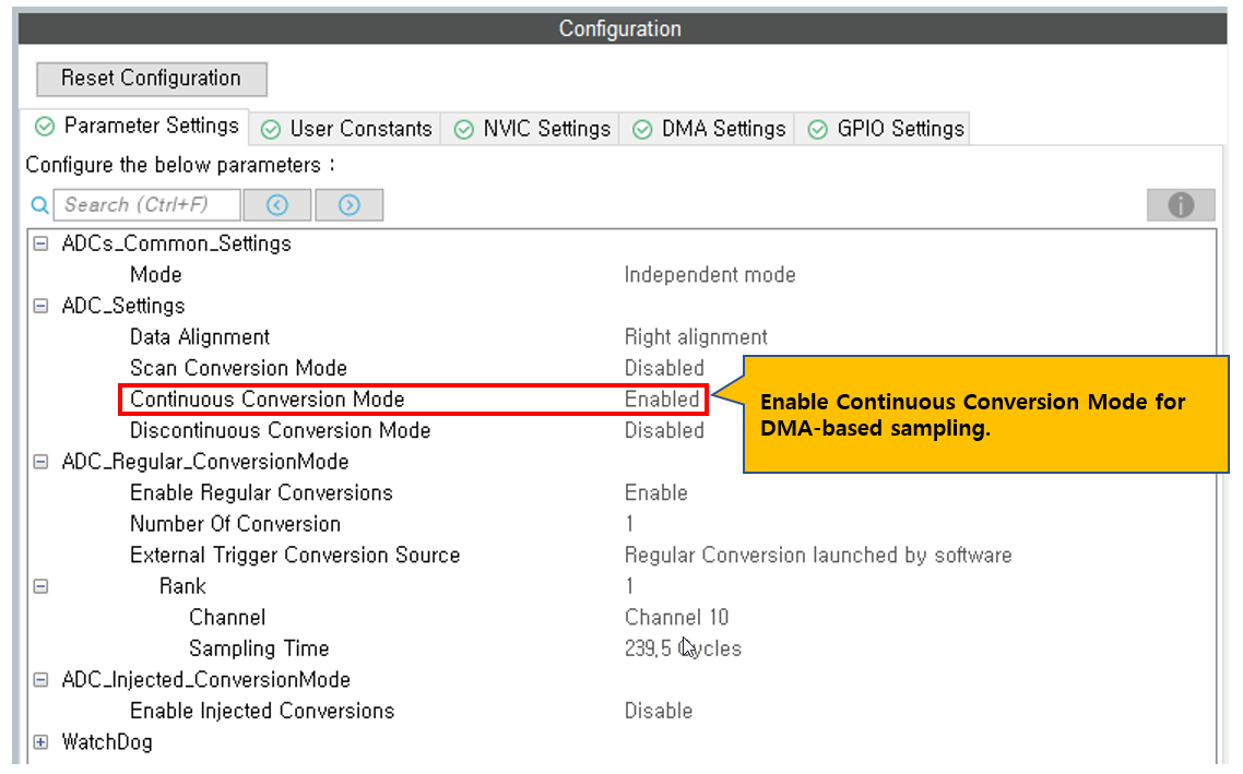
In the Parameter Settings, the basic ADC configuration remains the same as the Polling method, but Continuous Conversion Mode must be changed to Enable so that the ADC continuously performs conversions.
With this setting, once the ADC starts, it can continuously sample without additional CPU intervention.
DMA Settings Configuration
To automatically transfer ADC conversion data to memory without CPU intervention, DMA configuration is required.
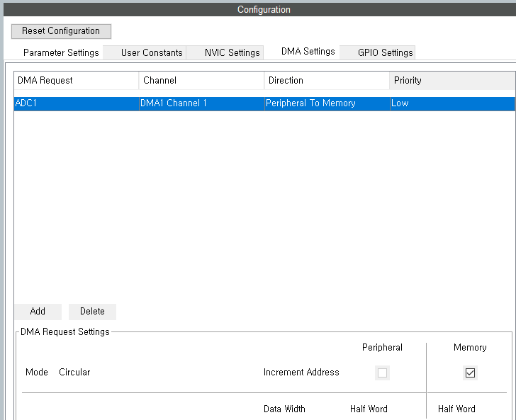
In the CubeMX DMA Settings tab, add a DMA channel connected to ADC1.
For DMA Request, select the default DMA channel connected to ADC1. In STM32F103, it is automatically assigned to DMA1 Channel 1.
The data transfer direction should be set to Peripheral to Memory, which means the ADC data register transfers data to memory.
Set the DMA mode to Circular Mode.
Circular Mode repeatedly stores ADC data into the buffer and returns to the beginning once the buffer is full.
With this setting, the ADC continuously performs conversions and DMA continuously stores the ADC data into the memory buffer.
Set Peripheral Increment to Disable.
Since the ADC data register address is fixed, address increment is not required.
Set Memory Increment to Enable.
This is necessary because ADC data must be stored sequentially in the buffer.
Set the data width of both Peripheral and Memory to Half Word (16-bit).
Although STM32 ADC has 12-bit resolution, the data is stored in 16-bit units.
Set Priority to Low.
Since PT100 temperature measurement does not require high-speed response, low priority is sufficient.
With this configuration, ADC and DMA work together so that the CPU does not need to directly read ADC data, enabling continuous sampling.
Below is the configuration screen.
After completing the configuration, generate the project code, and CubeMX will automatically generate the DMA initialization code.
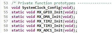
In the main.c file, you can verify that the MX_DMA_Init() function has been added along with MX_ADC1_Init().
The DMA initialization function must be called before ADC initialization, and after that, ADC DMA operation can be started.
Code Implementation
Now let’s write the user code for ADC DMA operation.
For project modularization, the ADC-related functions were separated into a dedicated module.
Create pt100_dmaadc.h and pt100_dmaadc.c files to implement ADC DMA initialization, average data processing, and voltage conversion functions.
This structure has the advantage of being expandable later when adding PT100 temperature conversion and calibration functions.
Header File(pt100_dmaadc.h)
Below is the code for pt100_dmaadc.h.
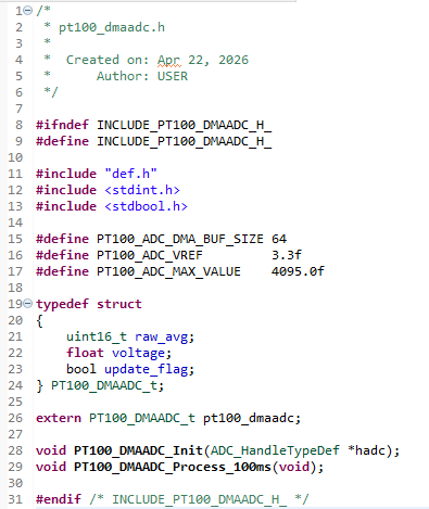
The buffer size was defined as 64 samples, and DMA continuously stores ADC data while cycling through this buffer.
The ADC reference voltage was defined as 3.3V, and the maximum value of the 12-bit ADC was defined as 4095.
The structure PT100_DMAADC_t consists of:
- Average ADC raw value (
raw_avg) - Calculated voltage (
voltage) - Data update flag (
update_flag)
Using this structure allows all ADC processing results to be managed as a single object, improving code readability and maintainability.
The initialization function PT100_DMAADC_Init() starts ADC DMA operation.
The processing function PT100_DMAADC_Process_100ms() calculates the average value of the DMA buffer at regular intervals and converts it into voltage.
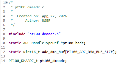
Source File(pt100_dmaadc.c)
The functions and variables declared in the header file are implemented in the source file.
First, include the header file and declare a static ADC handle pointer.
This pointer stores the ADC handle passed from the initialization function and is used later when starting DMA.
Also define the DMA buffer that stores ADC data and the structure variable that stores average ADC values and converted voltage values.
Since the DMA buffer is only used internally in the module, it is declared as static to restrict external access.
The measurement result structure is declared as a global variable so that it can be accessed by other modules.
Next, implement the initialization function for reading ADC through DMA.
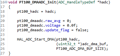
In the initialization function, the ADC handle is stored in an internal variable, and the measurement result structure is initialized.
raw_avg and voltage are initialized, and update_flag is set to false, indicating that no valid measurement data exists yet.
Then the HAL_ADC_Start_DMA() function is called to start ADC DMA operation.
The first argument is the ADC handle, the second argument is the start address of the DMA buffer, and the third argument is the buffer size.
Once this function is called, the ADC starts continuous conversion, and DMA automatically stores the conversion results into the buffer.
Since DMA is configured in Circular Mode, once the buffer is full, it returns to the beginning and continuously updates the data.
This means the CPU does not need to directly read ADC data and can always check the latest ADC data from memory.
The next function is called every 100ms to process the ADC data stored in the DMA buffer.
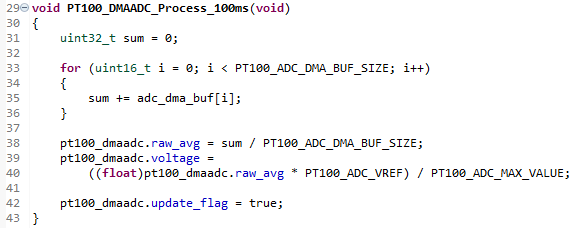
DMA continuously stores ADC data into the buffer, but since individual samples may be affected by noise, averaging multiple samples provides a more stable measurement.
First, all ADC values in the buffer are accumulated.
Then the accumulated value is divided by the buffer size to calculate the average ADC raw value and store it in raw_avg.
Next, the average ADC value is converted into the actual voltage and stored in the voltage variable.
The voltage conversion uses the ADC reference voltage (3.3V) and the 12-bit ADC maximum value (4095).
Finally, update_flag is set to true to indicate that new measurement data is ready.
In the main loop, this flag can be checked to perform follow-up processing only when new data is available.
With this structure, sampling is handled automatically by DMA, and the CPU only performs periodic averaging calculations, significantly reducing CPU load.
Application Program
Now that the ADC DMA module is completed, it can be called from the Application program to process ADC data.
The Application program is implemented in app.c.
First, in the initialization function appInit(), call PT100_DMAADC_Init(&hadc1) to start ADC DMA operation.
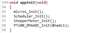
Once this function is called, the ADC starts continuous conversion, and DMA automatically stores ADC data into the memory buffer.
Then in the main loop appMain(), call PT100_DMAADC_Process_100ms() every 100ms to calculate the average value of the DMA buffer and convert it into voltage.
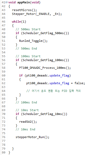
When new measurement data is ready, update_flag is set to true, and the Application program can perform follow-up processing such as temperature conversion or PID control input.
With this structure, ADC sampling is automatically handled by DMA, and the CPU only performs periodic average calculations and follow-up processing, reducing overall system load.
ADC Reading Experiment
After completing the firmware, build the project and download it to the STM32 in Debug mode.
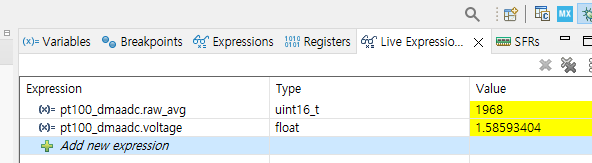
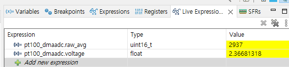
To verify the ADC DMA operation in real time, monitor the pt100_dmaadc.raw_avg and pt100_dmaadc.voltage variables updated by the PT100_DMAADC_Process_100ms() function in Live Expression.
When the program is resumed, ADC DMA continuously performs sampling, and the average ADC value and converted voltage are updated every 100ms in real time.
Below is the measurement result when the input resistance is 99.3Ω.
- Average ADC Raw: 1968
- Calculated Voltage: 1.5859V
Below is the measurement result when the input resistance is 149.3Ω.
- Average ADC Raw: 2937
- Calculated Voltage: 2.3668V
Below is the comparison table between the analog board output voltage and the ADC DMA reading.
| Condition | Resistance (Ω) | Input Voltage (V) | Board Output (V) | ADC Raw | ADC Voltage (V) |
|---|---|---|---|---|---|
| Reference 1 | 99.3 | 0.1155 | 1.617 | 1968 | 1.586 |
| Reference 2 | 149.3 | 0.171 | 2.392 | 2937 | 2.367 |
| Open | ∞ | – | 3.3 | 4080 | 3.29 |
For both 99.3Ω and 149.3Ω, the ADC voltage values were measured close to the board output voltage, and the ADC raw values increased proportionally with resistance.
Also, in the open condition, the ADC raw value increased up to 4080, confirming that the input reached near the upper saturation level.
This verifies that the DMA-based ADC sampling and averaging structure operates correctly.
Conclusion
In this experiment, the STM32 ADC DMA function was used to read the output voltage of the PT100 analog interface board.
In the previous Polling method, the CPU had to directly read ADC values, and in the Time-Distributed Sampling method, although the sampling workload was distributed over time, the CPU still had to directly handle ADC processing.
By applying the DMA method, ADC sampling and memory storage are performed automatically, and the CPU only needs to perform periodic averaging calculations and follow-up processing.
Through this experiment, it was confirmed that the DMA-based ADC sampling structure operates correctly and that ADC values change stably according to input resistance changes.
This structure can be applied not only to PT100 temperature measurement but also to various analog sensor inputs and has the advantage of efficiently using CPU resources in embedded systems where multiple tasks run simultaneously.
PT100 Temperature Measurement Series
PT100 temperature measurement series organized step-by-step from Analog Front End design to STM32 ADC Polling, Time-Distributed Sampling, ADC DMA implementation, and 3-wire PT100 constant current drive design.
Part 1: AFE (Analog Front End) Design for PT100 Temperature Measurement
PT100 Temperature Measurement AFE (Analog Front End) Design
Part 2: Reading PT100 Signals Using STM32F103 ADC (Polling Method)
Reading PT100 Signals with STM32F103 ADC (Polling Method Experiment)
Part 3: STM32 ADC Time-Distributed Sampling Design Method
STM32 ADC Time-Distributed Sampling Design Method
Part 4: Implementing PT100 Temperature Measurement Using STM32 ADC DMA
Part 5: 3-Wire PT100 Constant Current Driven AFE Design (TLV9062 + INA826)
3-Wire PT100 Constant Current Driven AFE Design(TLV9062+INA826)

“Implementing PT100 Temperature Measurement Using STM32 ADC DMA”에 대한 1개의 생각