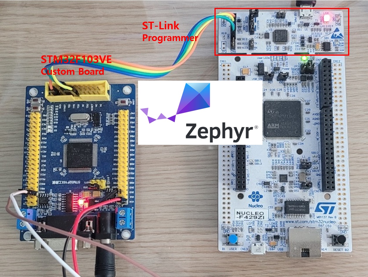
Introduction
The field of embedded systems continues to expand as technology and hardware evolve.
In the past, embedded systems were primarily designed for simple control applications. Today, however, they are expected to provide not only reliable control but also network connectivity and high-level computing capabilities.
As embedded systems become larger and more complex, the importance of operating systems (OS) continues to grow.
In the previous series, we explored the core features of FreeRTOS, one of the most widely used real-time operating systems, including Tasks, Semaphores, Queues, and Mutexes.
In this new series, we will introduce Zephyr RTOS, which extends beyond the traditional capabilities of FreeRTOS. Zephyr is more than just an RTOS—it is a comprehensive embedded software platform that integrates Device Tree, a Driver Framework, and a Build System, enabling developers to build applications for a wide variety of MCUs and SoCs within a unified framework.
In this first tutorial, we will create a Zephyr Custom Board for the STM32F103VE, manually port it to Zephyr, and develop a simple LED Blinking application. Through this hands-on exercise, you will gain a solid understanding of the basic structure of a Zephyr project, the build process, and how Zephyr Custom Boards are created and integrated into the development workflow.
Introducing Zephyr RTOS
Zephyr RTOS is an open-source real-time operating system (RTOS) hosted by the Linux Foundation. It supports a wide range of MCUs and SoCs and has evolved beyond a traditional RTOS into a comprehensive embedded software platform.
Zephyr supports not only ARM Cortex-M processors but also a variety of architectures, including RISC-V and Xtensa. It provides a unified development framework for boards from many semiconductor vendors, such as STMicroelectronics (STM32), NXP, Nordic Semiconductor, and Espressif.
While a traditional RTOS mainly focuses on real-time services such as Tasks, Semaphores, and Queues, Zephyr also includes essential development components such as Device Tree (DTS), a Driver Framework, Kconfig, and a CMake-based build system. These components enable developers to manage an entire embedded project within a single, consistent framework.
Zephyr also provides standardized driver APIs for peripherals such as UART, SPI, I²C, ADC, and PWM. As a result, application code often requires little or no modification when migrating between different MCU families, making it highly portable and reusable.
Key Features of Zephyr
- Open-source RTOS hosted by the Linux Foundation
- Supports a wide variety of MCUs and SoCs
- Hardware configuration using Device Tree (DTS)
- Feature configuration through Kconfig
- CMake- and West-based build system
- Standardized driver APIs (GPIO, UART, SPI, I²C, ADC, PWM, etc.)
- Comprehensive RTOS services, including Threads, Semaphores, Mutexes, and Message Queues
One of Zephyr’s greatest strengths is that it is more than just an RTOS. It provides a complete embedded software platform that integrates project configuration, hardware description, driver management, and application development into a unified ecosystem.
For more information about Zephyr, please visit the official project website.
Zephyr Project Official Website
In this tutorial series, we will create a custom STM32F103 board and manually port it to Zephyr step by step. Along the way, you will naturally learn the structure of a Zephyr project, its build system, and the role of the Device Tree.
Preparing the Toolchain
Several development tools are required to build Zephyr projects. In this tutorial, we will use the following toolchain.
| Tool | Purpose |
|---|---|
| West | Zephyr project management and build tool. Used to create projects, build applications, and flash firmware. |
| CMake | Generates build configuration files and configures the project. |
| Python | Executes West and Zephyr build scripts. |
| Ninja | Performs the actual project build. |
| STM32CubeProgrammer | Downloads firmware to the STM32 MCU. |
| Visual Studio Code | Source code editor used for development. |
Unlike some embedded development environments, Zephyr is not tied to a specific IDE. Instead, each tool has its own responsibility, while West integrates them into a unified development workflow.
The tools listed above form the basic development environment required for Zephyr projects. Since the Zephyr SDK requires a separate installation and verification process, we will cover it in detail in the next section.
The installation procedure for each tool may vary depending on your operating system and software versions. Therefore, this tutorial does not cover the installation steps in detail. For the latest installation instructions, please refer to the Getting Started Guide on the official Zephyr website.
The official Getting Started Guide provides comprehensive instructions, from installing the required toolchain to setting up the complete development environment.
The screenshot below shows the versions of the toolchain installed on the author’s computer, as verified from the Visual Studio Code PowerShell.
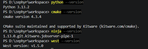
The current development environment satisfies all of the minimum toolchain requirements specified in the official Zephyr Getting Started Guide.
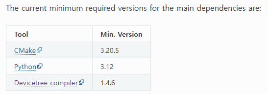
The Device Tree Compiler (DTC) is automatically invoked during the Zephyr build process, so a separate verification step is unnecessary. If a project builds successfully, it generally indicates that DTC has been installed correctly and is functioning as expected.
With the basic toolchain now in place, the next step is to install the Zephyr SDK, which is the core component of the Zephyr development environment. In the following section, we will install the SDK and verify that it is working correctly.
Installing the Zephyr SDK
Now it’s time to download and install the Zephyr SDK.
In this chapter, we will go through the installation process step by step, including installing 7-Zip, downloading the Zephyr SDK, and installing the SDK itself.
Whether the SDK has been installed correctly will be verified in the next chapter when we set up the workspace and perform an actual project build.
Installing 7-Zip
The Zephyr SDK is distributed as a compressed archive. Therefore, you will need an archive extraction tool before installing the SDK.
Although many archive utilities are available for Windows, this tutorial recommends 7-Zip, which is also widely used throughout the official Zephyr documentation.
You can download 7-Zip from the link below.
Download the version that matches your operating system. For most modern PCs, the 64-bit Windows x64 version is the appropriate choice.
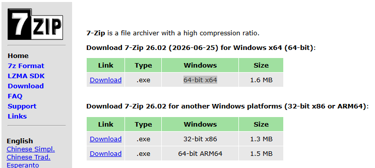
Run the installer and click Install to proceed with the default settings. No special configuration is required. Once the installation is complete, click Close to exit the installer.
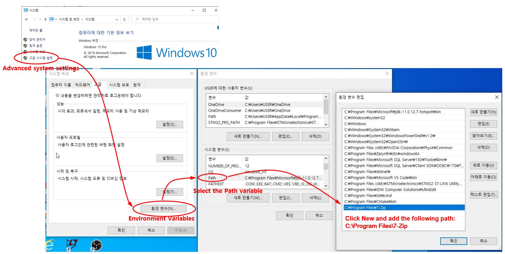
After the installation, make sure that the 7-Zip executable has been added to your system PATH so that the Zephyr SDK installer can invoke it during the installation process.
If 7-Zip is not included in the PATH environment variable, the Zephyr SDK installation may fail because the installer will be unable to locate and execute the 7-Zip program.
In Windows, you can access the PATH environment variable by following either of these paths:
Control Panel → System → Advanced system settings → Environment Variables
or
Settings → System → About → Advanced system settings → Environment Variables
In the Environment Variables dialog, select the Path variable and click Edit.
Verify that the folder where 7-Zip is installed (for example, C:\Program Files\7-Zip) is listed. If it is not, click New, add the folder path, and then click OK to save the changes.
Downloading the Zephyr SDK
Now let’s download the Zephyr SDK.
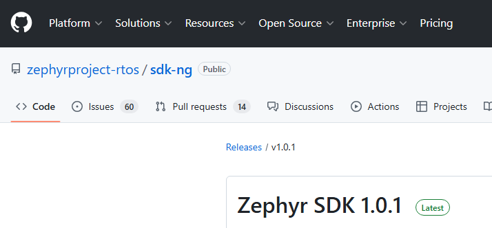
The official Zephyr website provides installation instructions, while the actual SDK packages are distributed through GitHub Releases.
Click the link below to open the latest Zephyr SDK Release page.
Download the package that matches your operating system. For this tutorial, select the GNU x86-64 package for Windows, as highlighted below.
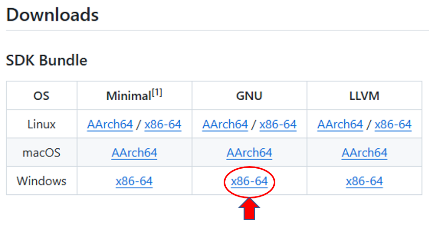
The downloaded archive file is named zephyr-sdk-1.0.1_windows-x86_64_gnu.7z.
The SDK Bundle is available in three editions: Minimal, GNU, and LLVM. Since most Zephyr examples for STM32 and many other MCU platforms use the GNU Toolchain, this tutorial will use the GNU edition.
In the next section, we will install the Zephyr SDK and verify that it has been installed correctly.
It is recommended to keep the downloaded SDK archive in your Zephyr workspace or another dedicated folder for future use.
In this tutorial, the SDK archive is stored in a dedicated Zephyr folder, as shown below.

After extracting zephyr-sdk-1.0.1_windows-x86_64_gnu.7z into the Zephyr folder, a directory named zephyr-sdk-1.0.1 will be created. This directory contains all the files required to install the Zephyr SDK.
Note
The screenshots in this article were captured in a separate
Zephyr_Testfolder to reproduce the installation process from scratch. In your actual development environment, you can follow the same procedure using your regular Zephyr workspace (for example,D:\Zephyr).
Installing the SDK
Open the extracted zephyr-sdk-1.0.1 directory. You will find the following files:
setup.cmdsetup.ps1sdk_toolchain_install.bat- Other SDK files and directories
On Windows, run setup.cmd to start the Zephyr SDK installation.
During the installation, the setup program will prompt you to select several installation options. Use the following settings:
| Option | Selection | Description |
|---|---|---|
| Install GNU toolchain | Y | Installs the GNU GCC toolchain used by STM32 and most Zephyr projects. |
| Install LLVM toolchain | N | Skips the LLVM/Clang toolchain, which is not used in this tutorial. |
| Install host tools | Y | Installs the host tools required for building Zephyr applications. |
| Register Zephyr SDK CMake package | Y | Registers the Zephyr SDK so that CMake can locate it automatically. |
After all options have been selected, the installer will copy the required files and configure the SDK. Once the installation is complete, the Zephyr SDK is ready to use.
After the installation is complete, a message similar to the following may appear:
SKIPPED: Windows host tools are not available yet.At the time of writing, the Windows Host Tools package is not included in the Zephyr SDK. Therefore, the installer automatically skips this step.
If this message appears, the Zephyr SDK has still been installed successfully and no additional action is required.
When the installation finishes, the following message will be displayed:
Press any key to exit...Press any key to close the installer.
The Zephyr SDK has now been installed successfully.
The installation will be verified in the next chapter by creating a Zephyr workspace and building a sample project. This confirms that the SDK has been installed correctly and is properly recognized by the Zephyr build system.
Setting Up the Workspace
Preparing the Zephyr Workspace
Now that the Zephyr SDK has been installed, it’s time to set up a workspace for Zephyr development.
Unlike a traditional IDE, Zephyr is not organized around a single project. Instead, it uses a workspace that contains the Zephyr source tree, user applications, custom boards, and other development resources in a single location.
A well-organized workspace makes it easier to manage multiple projects and helps keep user applications independent of future Zephyr updates.
The workspace used in this tutorial is organized as shown below.
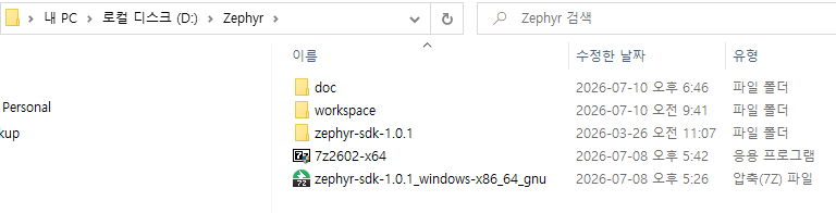
The following folders and files are located in the top-level Zephyr directory:
- doc – Documentation and reference materials
- workspace – Working directory for the Zephyr source tree and user projects
- zephyr-sdk-1.0.1 – Installed Zephyr SDK
- 7z2602-x64.exe – 7-Zip installer
- zephyr-sdk-1.0.1_windows-x86_64_gnu.7z – Downloaded Zephyr SDK archive
Organizing the development environment in this way makes it easier to manage the SDK and multiple projects. It also simplifies setting up a new development environment or moving your workspace to another computer.
In the next section, we will create a Zephyr workspace inside this working directory.
Creating the Workspace
The workspace is created using the west init workspace command. After the workspace has been created, running west update downloads the Zephyr kernel, modules, and other required source code from GitHub.
The diagram below illustrates how the Zephyr SDK and the workspace work together during the build process.
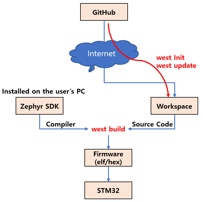
The Zephyr development environment consists of two main components: the Zephyr SDK and the workspace.
- The Zephyr SDK provides the compiler, linker, and other toolchain components required to build Zephyr applications.
- The workspace contains the Zephyr kernel, drivers, modules, and user applications.
west initandwest updatedownload the Zephyr source code from GitHub into the workspace.west builduses the source code in the workspace together with the Zephyr SDK toolchain to generate firmware images (.elfand.hex).- The generated firmware is then programmed onto the target MCU, such as an STM32 device.
It is important to understand that the Zephyr SDK and the workspace serve different purposes. The SDK provides the build tools, while the workspace contains the source code that you develop and build.
Now let’s create the workspace by running the west init workspace command. In this tutorial, all commands are executed from the PowerShell terminal in Visual Studio Code.
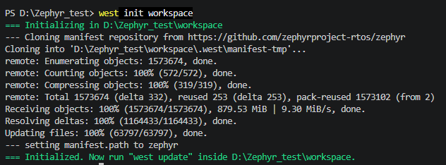
Running the following command creates the workspace directory and initializes the manifest repository, which is used to manage Zephyr projects.
west init workspaceNow run "west update" inside D:\Zephyr_Test\workspace.west update command to download the Zephyr kernel, modules, and other required source code.First, change to the newly created workspace directory and execute:
cd workspace
west updateDepending on your Internet connection, the initial download may take several minutes to complete.
After west update finishes, the workspace will contain the repositories required for Zephyr development, as shown below.
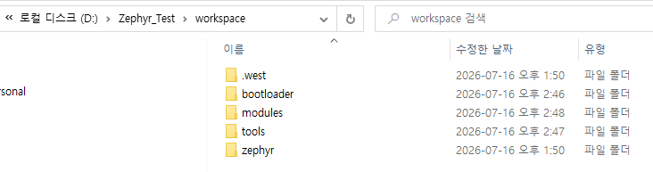
The purpose of each folder is as follows:
.west– Stores the workspace configuration and West metadata.zephyr– Contains the Zephyr kernel and core source code.modules– Contains the external modules used by Zephyr.bootloader– Contains bootloader-related source code, including MCUboot.tools– Contains various tools required for Zephyr development.
Next, install the Python packages required by Zephyr.
cd D:\Zephyr_Test\workspace
pip install -r zephyr\scripts\requirements.txt
This command installs the Python packages required for building Zephyr applications, processing the Device Tree, flashing firmware, and other development tasks. It only needs to be run once for each development environment.
The basic Zephyr workspace setup is now complete.
Next, we will create a custom board and register it with Zephyr.
Creating a Custom Board
At this point, we have finished setting up the Zephyr development environment and created the workspace.
In this tutorial, we will use an STM32F103VE development board. Although this board is inexpensive and readily available from online marketplaces such as AliExpress, it is not included in Zephyr’s list of officially supported boards.
To use this board with Zephyr, we must create and register a new board definition. This process is referred to as creating a custom board, and it is one of the most common approaches used in real-world embedded product development.
A custom board does not necessarily mean a PCB that you designed yourself. In Zephyr, it refers to any board that is not officially supported and therefore requires its own board definition.
The photograph below shows the development board used throughout this tutorial.
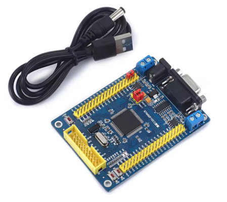
In the following steps, we will add a new board to the workspace so that it can be used by Zephyr. We will then create the required board name and directory structure.
The same procedure can also be applied to custom STM32 boards designed for your own products.
First, create a directory under the workspace to store your custom boards and user projects.
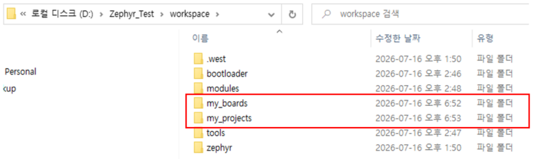
Create a directory named my_projects to store your application projects.
Also create a directory named my_boards, which will contain your custom board definitions. Zephyr searches this directory for additional board definitions and recognizes any boards registered here.
Inside my_boards, create the following directory structure.
Zephyr searches for custom boards under the boards directory. Therefore, create a boards directory inside my_boards, and then create a my_f103ve directory beneath it.
It is recommended that the board directory name match the board name that will be registered with Zephyr. In this tutorial, we will use my_f103ve as the board name.
Next, create the basic files required to define the board. Additional files will be added later when configuring the Device Tree.
board.yml– Defines the basic information for the board.Kconfig.my_f103ve– Contains the board-specific Kconfig options.my_f103ve_defconfig– Defines the default board configuration.
Create these three empty files in the my_f103ve directory. We will edit each file in the following steps.
Let’s begin with board.yml.
The board.yml file defines the basic information required to register a new board with Zephyr. It specifies the board name, display name, and the target SoC used by the board.
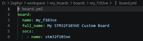
The fields in board.yml have the following meanings:
name– The board name used internally by Zephyr.full_name– A human-readable name displayed to users.socs– Defines the target MCU (SoC) used by the board.
Next, create the Kconfig.my_f103ve file.
This file specifies the SoC (System on Chip) associated with the my_f103ve board when it is selected in Zephyr.
Add the following content:
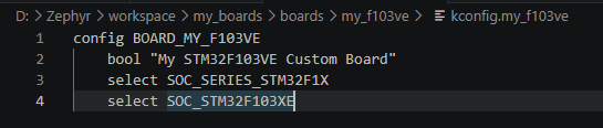
The configuration options are described below:
BOARD_MY_F103VE– Defines the Kconfig option used to select themy_f103veboard.bool– Specifies the board name displayed in the Kconfig menu.SOC_SERIES_STM32F1X– Selects the STM32F1 series.SOC_STM32F103XE– Specifies the STM32F103XE MCU.
As a result, when the my_f103ve board is selected, Zephyr automatically configures the project for an STM32F103XE device in the STM32F1 series.
Finally, create the my_f103ve_defconfig file.
The my_f103ve_defconfig file contains the default Kconfig settings for the board. At this stage, no additional configuration is required, so simply add the following comment:

Although the file is currently empty, it can be used later to define default board settings such as clock configuration, console settings, and other board-specific options.
The basic files required to define the custom board are now in place. The next step is to verify that Zephyr can recognize the new board.
Run the following command in the PowerShell terminal in Visual Studio Code:
west boards --board-root=D:\Zephyr\workspace\my_boards | findstr my_f103veIf the board name my_f103ve appears in the output, the board has been successfully registered with Zephyr.
The --board-root option tells Zephyr where to search for custom board definitions in addition to its built-in boards.

As shown above, the board name my_f103ve appears in the search results, confirming that the board has been successfully registered with Zephyr.
At this stage, the board definition is not yet complete. Hardware-specific information such as the memory layout, clock configuration, and LED pin assignments has not yet been added. This step simply verifies that Zephyr recognizes the board name and its basic registration information.
So far, we have completed the process of registering a new board with Zephyr.
In the next section, we will create the Device Tree (DTS) files to define the board’s actual hardware configuration.
Device Tree (DTS) and Board Configuration
In the previous chapter, we registered the my_f103ve custom board with Zephyr and verified that it could be recognized successfully.
However, at this stage, only the board name has been registered. Zephyr still has no information about the board’s hardware, such as the Flash size, SRAM size, clock configuration, or LED pin assignments.
This hardware information is defined using the Device Tree (DTS).
In this chapter, we will create the my_f103ve.dts file and the related configuration files so that Zephyr can understand the hardware configuration of the board.
A Zephyr Device Tree consists of three types of files:
- DTS – The board-specific Device Tree source file.
- DTSI – Shared Device Tree include files that provide SoC- or board-family-specific hardware definitions.
- Overlay – Application-specific Device Tree modifications that override or extend the base configuration.
The following diagram illustrates how these files work together during the build process.
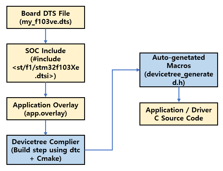
The diagram above illustrates the overall Device Tree processing flow in Zephyr.
- Board DTS (
my_f103ve.dts) defines the hardware configuration that is specific to the board. - SoC Include (
stm32f103Xe.dtsi) provides the common hardware definitions shared by all STM32F103XE-based boards. - Application Overlay (
app.overlay) allows an application to modify or extend the base Device Tree configuration. - During the build process, the Device Tree Compiler (DTC) merges these files into a single Device Tree.
- Zephyr then generates
devicetree_generated.h, which is used by the application and drivers to access the hardware configuration.
As a result, application developers do not need to parse the Device Tree directly. Instead, they access the hardware information through the APIs and macros generated by Zephyr.
In this tutorial, we will create only my_f103ve.dts. The stm32f103Xe.dtsi file is already provided by Zephyr, and app.overlay is not required for this simple LED Blinking example.
The diagram above has been adapted from the following reference and simplified for this tutorial.
How Zephyr RTOS Builds and Uses the Devicetree
Now let’s create the my_f103ve.dts file.
The first step is to include the DTSI (Device Tree Include) file that contains the common hardware definitions for the target SoC.
The stm32f103Xe.dtsi file already defines the common hardware resources of the STM32F103XE MCU, including the CPU, Flash, SRAM, GPIO, UART, and timers.
Therefore, when creating a custom board, you can reuse this file and only define the board-specific hardware configuration, such as the LED, clock, and pin assignments.
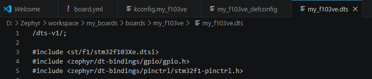
The example above includes three header files. The purpose of each file is described below.
#include <st/f1/stm32f103Xe.dtsi>
Includes the common Device Tree definitions for the STM32F103XE MCU.#include <zephyr/dt-bindings/gpio/gpio.h>
Provides GPIO-related constants, such asGPIO_ACTIVE_LOWandGPIO_ACTIVE_HIGH, which are used when defining GPIO properties in the Device Tree.#include <zephyr/dt-bindings/pinctrl/stm32f1-pinctrl.h>
Provides the pin control definitions used to configure STM32F1 pin assignments in the Device Tree.
Configuring the Root Node
Next, let’s define the root node of the Device Tree.
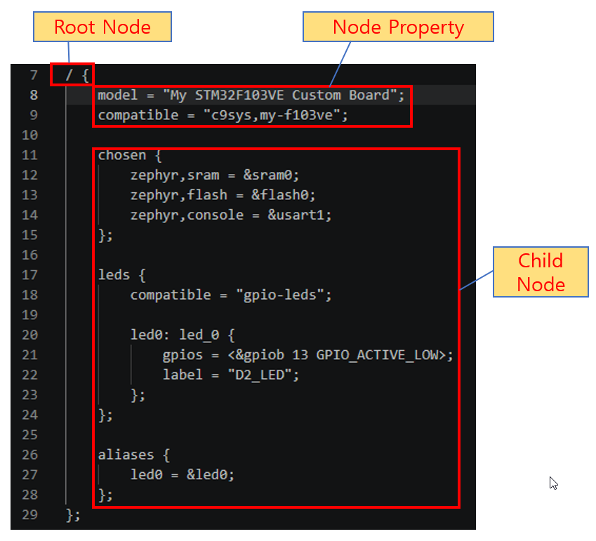
The root node of a Device Tree consists of node properties and child nodes, as shown in the figure above.
Nodes can also be defined outside the root node. However, these do not create new nodes. Instead, they reference existing nodes and override their properties. The two cases can be distinguished as follows.
Inside the root node (/), you define information that is specific to the board. Examples include model, compatible, chosen, leds, and aliases.
In contrast, nodes outside the root node—such as &usart1, &rcc, and &pll—reference the common MCU hardware nodes that are already defined in stm32f103Xe.dtsi and override only the properties required for the board.
In other words, the root node is where you define the board itself, while nodes outside the root node are used to customize the common MCU hardware for that board.
The current root node contains two properties:
modelcompatible
The purpose of each property is described below.
model– A human-readable name for the board.compatible– A string used by Zephyr and its drivers to identify the board.
The current root node also contains three child nodes:
chosenledsaliases
The purpose of each child node will be explained in the following sections.
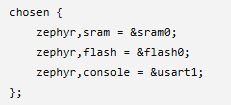
The chosen node is a reserved node used to specify the hardware devices that Zephyr uses by default.
In this tutorial, the chosen node is used to specify the default SRAM, Flash, and Console (UART) devices.
During the build process, Zephyr uses this information to initialize the memory layout and the default console.
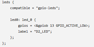
The leds node defines the LEDs connected to the board.
Within this node, you specify the GPIO controller, pin number, active level (high or low), and a label for each LED.
In this tutorial, the LED connected to PB13 is registered as led0.
Applications can then access this LED using the alias led0.
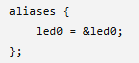
The aliases node defines convenient aliases for frequently used Device Tree nodes.
By using aliases, application code can refer to hardware devices with simple, meaningful names instead of their full Device Tree node names. This improves both code readability and portability.
In this tutorial, we define the alias led0 so that the application can easily reference the onboard LED.
Note
The Device Tree supports many child nodes in addition to chosen, leds, and aliases, including buttons, gpio-keys, and pwmleds.
In this LED Blinking tutorial, we use only these three fundamental child nodes. Additional child nodes will be introduced later in the UART, Button, and PWM tutorials.
Configuring the Clock
Before the STM32F103VE board can operate correctly, the system clock must be configured.
The clock-related nodes are already defined in stm32f103Xe.dtsi. When creating a custom board, you simply reference these nodes and override the settings required for your hardware.
In this tutorial, we configure the following three nodes:
&clk_hse– Enables the external 8 MHz High-Speed External (HSE) crystal.&pll– Uses the HSE clock as the PLL input and multiplies it to generate a 72 MHz system clock.&rcc– Configures the system clock source and the AHB/APB bus clocks.
The configuration is shown below.
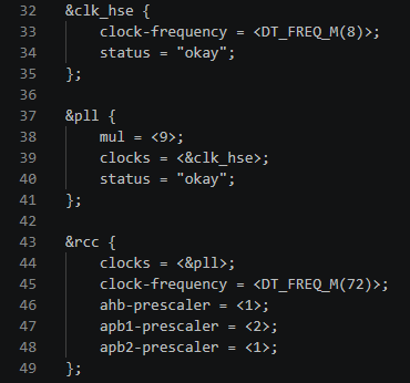
With these settings, the STM32F103VE runs at a 72 MHz system clock using the external 8 MHz HSE crystal.
With the Device Tree now complete, the basic hardware configuration for the custom board has been defined.
In future tutorials covering UART, SPI, I²C, and other peripherals, we will continue to extend the Device Tree by adding the nodes required for each feature.
Now that the Device Tree configuration is complete, it’s time to create the application that will blink the LED.
Creating the LED Blinking Application
So far, we have completed the custom board and Device Tree configuration.
Now it’s time to create an application that blinks the LED connected to PB13 using the Zephyr GPIO API.
The application project used in this tutorial has the following directory structure.
(project structure)
For this tutorial, all application code will be implemented in src/main.c.
Create the main.c file as shown below.
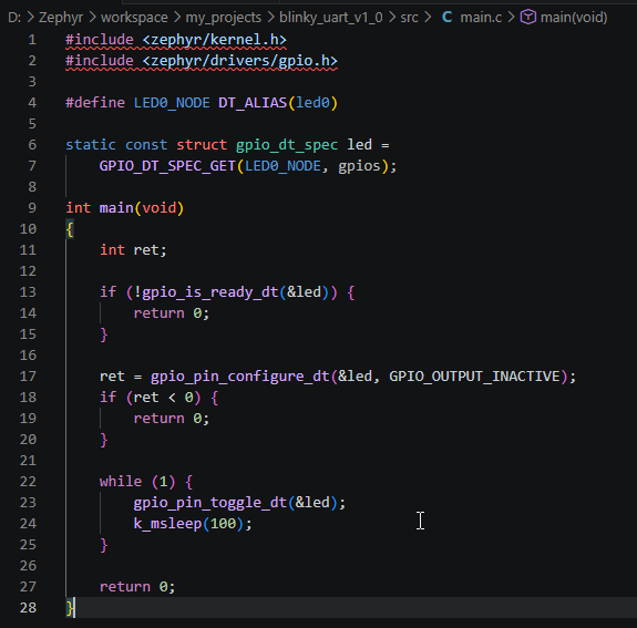
Let’s go through the code step by step.
Header Files

These header files provide access to the Zephyr Kernel API and the GPIO API.
The k_msleep() function is declared in kernel.h, while the GPIO-related functions and data structures are provided by gpio.h.
Retrieving LED Information from the Device Tree
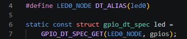
The DT_ALIAS(led0) macro retrieves the led0 alias that was defined earlier in the Device Tree aliases node.
The GPIO_DT_SPEC_GET() macro creates a gpio_dt_spec structure containing the GPIO controller, pin number, active level, and other GPIO configuration information defined in the Device Tree.
As a result, the application can use the GPIO configuration directly from the Device Tree without hardcoding the GPIO port number, pin number, or active level.
Initializing the GPIO
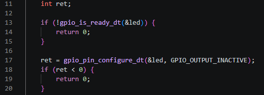
First, the application verifies that the GPIO device associated with the LED is ready for use. It then configures the GPIO pin as an output.
The initial output state is set to GPIO_OUTPUT_INACTIVE, so the LED starts in the OFF state.
Blinking the LED
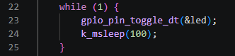
The application continuously toggles the LED inside an infinite loop.
The k_msleep() function is provided by the Zephyr Kernel and suspends the current thread for the specified number of milliseconds.
At this point, the LED blinking application is complete.
In the next chapter, we will build the project, generate the firmware, and download it to the STM32 board.
Building and Flashing the Application
The LED blinking application is now complete. The next step is to build the project and generate the firmware.
First, open the PowerShell terminal in Visual Studio Code and navigate to the project directory.

Run the following command to build the project.

The command-line options are explained below.
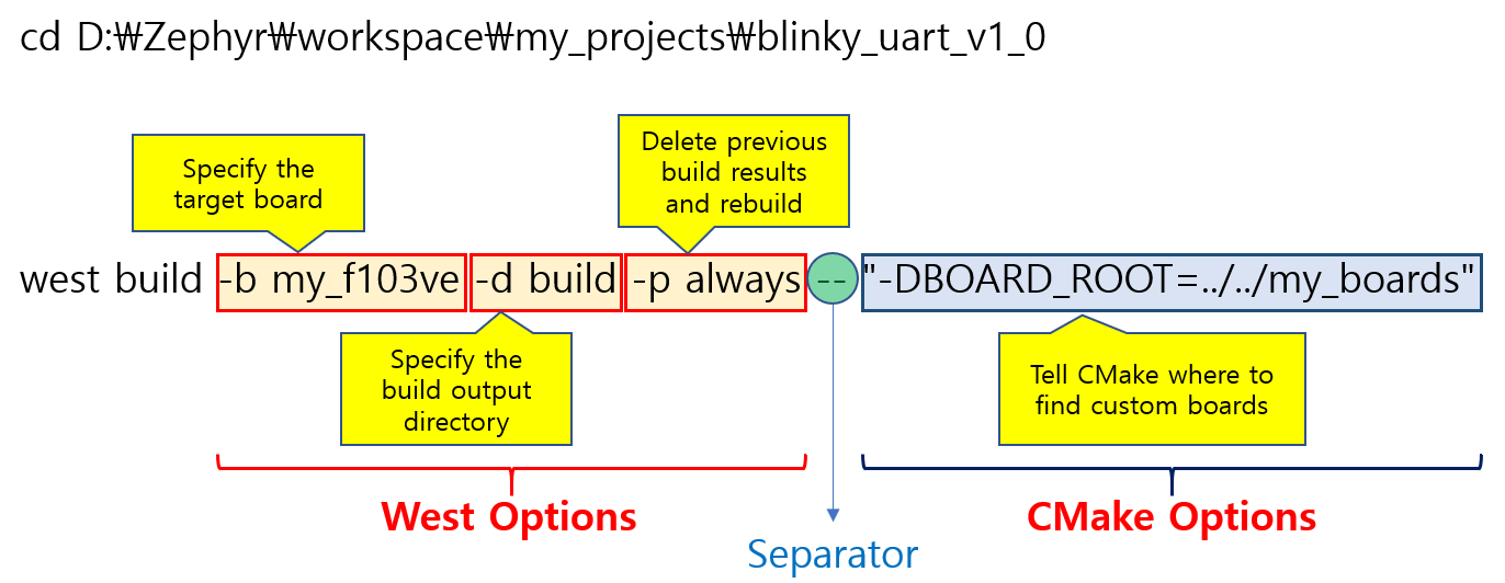
After the build completes successfully, a message similar to the following will appear at the end of the terminal output.

This message indicates that the project has been built successfully.
In particular, the last few lines display the location of the generated firmware together with the target board information.
From this output, you can verify the following:
- The
blinky_uart_v1_0.elffile has been generated successfully. - The project is configured for the
my_f103veboard. - The target MCU is
STM32F103XE.
With the firmware successfully generated, the next step is to program it onto the STM32F103VE board.
For officially supported boards, Zephyr typically allows the firmware to be programmed using the following command:

For officially supported boards, west flash is usually sufficient to program the firmware directly after a successful build.
However, west flash could not be used successfully with the STM32F103VE custom board used in this tutorial.
Although the ST-Link debugger was detected correctly, the flashing process failed because of a reset-related issue.
Therefore, this tutorial uses STM32CubeProgrammer to program the generated firmware onto the target board.
After the build is complete, the following firmware file is generated:

Open STM32CubeProgrammer, select the generated ELF file, and click Download to program the firmware onto the target board.
Note
To use Hardware Reset with a custom board, the NRST pin of the ST-Link must be connected to the NRST pin of the target MCU.
In STM32CubeProgrammer, change the Reset mode in the ST-Link settings to Hardware reset. This allows the firmware to be programmed reliably without manually pressing the Reset button.
If necessary, perform a Full Chip Erase before downloading the firmware.
In this tutorial, the Run after programming option did not start the application automatically after programming. Therefore, after the download is complete, click Disconnect and then press the Reset button on the target board to start the application.
If everything has been configured correctly, the LED connected to PB13 will blink periodically.
Note
west flashis the recommended flashing method in Zephyr and works correctly with officially supported boards, such as the Nucleo series.Since this tutorial uses a custom board that is not officially supported by Zephyr,
west flashcould not be used successfully. Therefore, STM32CubeProgrammer was used to program the firmware instead.
Results
After the build and programming process is complete, reset the board to start the application.
If everything has been configured correctly, the LED connected to PB13 will blink repeatedly at the interval specified in main.c.
In this tutorial, the LED is controlled using the following code:
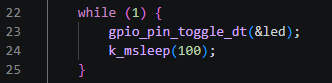
The gpio_pin_toggle_dt() function toggles the current state of the LED, while k_msleep(100) suspends the current thread for 100 ms.
As a result, the LED continuously turns ON and OFF at approximately 100 ms intervals.
Concusion
In this tutorial, we set up a complete Zephyr development environment and created our first Zephyr application by registering an STM32F103VE development board as a custom board.
We also learned how to describe the board hardware using the Device Tree and control an LED using the Zephyr GPIO API, completing the entire development flow from board definition to application development.
During this tutorial, we successfully verified the following:
- The custom board was successfully registered with Zephyr.
- The Device Tree correctly described the onboard PB13 LED.
- The LED was successfully controlled using the Zephyr GPIO API.
- The generated firmware ran correctly on the STM32F103VE board.
If your LED blinked successfully, it means that the complete development flow—from custom board creation and Device Tree configuration to application development and firmware programming—has been completed successfully.
Although Zephyr can also be installed using the Visual Studio Code Extension, this tutorial intentionally followed the manual setup process. By setting up the SDK, creating the workspace, registering a custom board, and building the project manually, you gain a much deeper understanding of how Zephyr works internally.
While the manual approach requires more effort initially, it provides a solid understanding of Zephyr’s architecture and build system. Concepts such as the workspace, West, Device Tree, and custom boards become much easier to understand, making it easier to work with more advanced Zephyr features in future projects.
This project will serve as the foundation for the upcoming tutorials in this series. In the following chapters, we will continue by exploring UART, Threads, Semaphores, and many other Zephyr RTOS features, gradually building toward more practical embedded applications.