Overview
In the previous practice, we created two tasks and verified the basic multitasking behavior of FreeRTOS. Although a single-core MCU can execute only one task at a time, the FreeRTOS scheduler switches between tasks very quickly, making it appear as though multiple tasks are running simultaneously.
However, in real-world applications, it is often not enough for tasks to run independently. One task may need to wait until a specific condition is met, while another task may need to notify it when a particular operation has completed. This mechanism of coordinating task execution timing or delivering events between tasks is called synchronization.
In this practice, we will use Binary Semaphore, one of the most common synchronization objects in FreeRTOS, to demonstrate how one task can signal an event to another task.
Through this example, we will learn the basic concept of semaphores and understand the roles of Give and Take operations.
What is a Semaphore?
In FreeRTOS, multiple tasks appear to run concurrently. However, in real-world applications, tasks often need to cooperate with one another rather than operate completely independently.
For example, one task may perform a sensor measurement, while another task should process the data only after the measurement has been completed. Alternatively, a task may need to wait until a button is pressed before continuing its operation. In these situations, one task must be able to notify another task that a specific event has occurred.
This is where a Semaphore is used.
A semaphore is not primarily intended for transferring data between tasks. Instead, it is a synchronization object used to deliver a signal indicating that a particular event has occurred.
By using semaphores, tasks can coordinate their execution timing efficiently without continuously polling for status changes, resulting in cleaner and more responsive application designs.
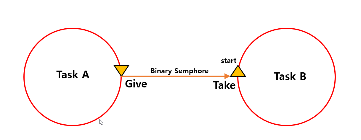
Assume that there are two tasks, Task A and Task B. Task B waits for a specific event to occur, while Task A gives a Binary Semaphore when its work is completed.
Task B remains blocked while waiting for the semaphore using the Take function. As soon as the semaphore is given, Task B is unblocked and begins execution.
In other words, a semaphore does not transfer data between tasks. Instead, it acts as a signaling mechanism that notifies another task that a particular event has occurred.
The sequence of operations shown in the diagram can be summarized as follows:
- Task B waits for the semaphore and enters the Blocked state.
- Task A completes a specific operation.
- Task A gives the semaphore.
- The waiting Task B takes the semaphore.
- Task B starts executing.
The link below provides an explanation of Binary Semaphores from the FreeRTOS official documentation.
In this practice, the role of Task A is performed by the LED2 Task, and the role of Task B is performed by the LED1 Task. After running a predefined number of times, the LED2 Task gives the semaphore. The LED1 Task waits for the semaphore and, once the signal is received, blinks the LED. This simple example demonstrates how semaphores can be used for task synchronization and event signaling in FreeRTOS.
System Operation Overview
In this practice, two tasks and a single Binary Semaphore are used to implement event signaling between tasks.
The diagram below illustrates the overall execution flow of the application.
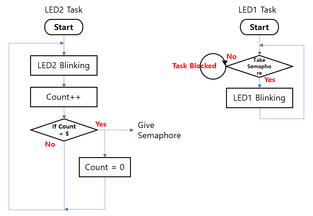
The LED2 Task runs periodically, blinks LED2, and increments a counter value.
When the counter reaches 5, the LED2 Task gives the Binary Semaphore, generating an event signal.
Meanwhile, the LED1 Task waits for the semaphore and remains in the Blocked state. While blocked, it does not consume CPU time and therefore does not waste processing resources.
Once the semaphore is given by the LED2 Task, the LED1 Task is immediately unblocked. It takes the semaphore and executes its assigned action, which is blinking LED1.
The operation can be summarized as follows:
- The LED2 Task runs periodically and increments a counter.
- The LED1 Task waits for the semaphore in the Blocked state.
- When the counter reaches 5, the LED2 Task gives the semaphore.
- The waiting LED1 Task takes the semaphore.
- LED1 blinks to indicate that the event has been received.
- The counter is reset, and the process repeats.
This example demonstrates one of the most common uses of a Binary Semaphore in FreeRTOS: event signaling between tasks. Rather than continuously checking a condition in a loop, a task can remain blocked until an event occurs, resulting in more efficient CPU utilization and cleaner program design.
The next step is to create a Binary Semaphore in code and make it available for use by multiple tasks.
In the following section, we will examine how to create a Binary Semaphore in FreeRTOS, where it should be declared, and how it is initialized before the scheduler starts running. This will provide the foundation for implementing task synchronization and event signaling in the subsequent examples.
Project Creation
The project used for this semaphore practice was created by copying the project developed in the previous exercise.
Since the project duplication procedure was explained in detail in Practice #1, it will not be repeated in this article.
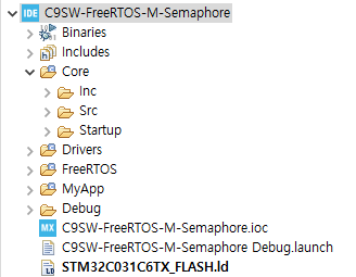
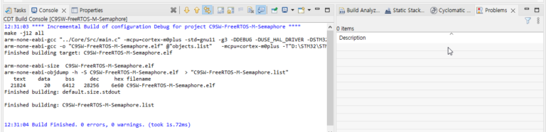
After copying the project from Practice #1, the project name was changed to C9SW-FreeRTOS-M-Semaphore.
Once the project was copied, a Build and Download were performed. As in the previous practice, the two LED tasks were confirmed to be blinking at different intervals.
This verifies that the project was copied successfully and is functioning correctly. We can now use this project as the foundation for adding semaphore-related functionality.
The figure below shows the project after it has been created.
Creating a Binary Semaphore
To use a Binary Semaphore in FreeRTOS, a semaphore object must first be created.
Since this project uses a manually ported FreeRTOS Kernel rather than the STM32CubeMX FreeRTOS middleware, the semaphore will also be created directly in code.
The first step is to declare a semaphore handle in the global variable section of main.c.
SemaphoreHandle_t ledSemaphore;This handle acts as a reference to the semaphore object and will be used by tasks when performing Give and Take operations.
The actual semaphore object will be created later during system initialization before the scheduler is started.
The figure below shows the location where the semaphore handle was declared in the project source code.
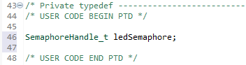
SemaphoreHandle_t is the handle type used by FreeRTOS to reference a semaphore object. Later, the LED2 Task will use this handle to give the semaphore, while the LED1 Task will use the same handle to take it.
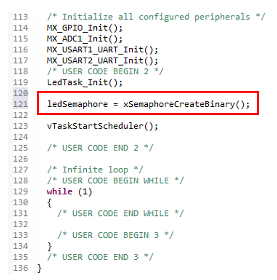
The next step is to create the Binary Semaphore before the scheduler starts running in the main() function.
ledSemaphore = xSemaphoreCreateBinary();In this practice, the semaphore is created after the tasks have been created by LedTask_Init(), but before the scheduler is started.
The function xSemaphoreCreateBinary() allocates and initializes a Binary Semaphore, returning a handle that can be used throughout the application. If the creation is successful, the returned handle is stored in ledSemaphore.
Creating synchronization objects before calling vTaskStartScheduler() is a common FreeRTOS practice, as it ensures that all required resources are ready before any task begins execution.
The figure below shows the actual code added to the project, where the semaphore is created immediately before the scheduler is started.
When xSemaphoreCreateBinary() is called, FreeRTOS creates a Binary Semaphore object and returns a handle that references the newly created object.
The semaphore created in this way can then be shared by multiple tasks within the application.
In this practice, the semaphore will be used as shown below:
LED2 Task
    |
    | Give
    v
Binary Semaphore
    ^
    | Take
    |
LED1 Task
When the LED2 Task has completed a predefined number of LED blink cycles, it will give the semaphore. The LED1 Task will remain waiting for the semaphore and, once it successfully takes it, will blink LED1 to indicate that the event has been received.
This simple structure demonstrates the fundamental signaling mechanism provided by Binary Semaphores, where one task generates an event and another task responds to it.
In the next section, we will implement the LED2 Task logic that increments a counter and gives the semaphore when the counter reaches a specified value.
Implementing the LED2 Task
In this section, we will modify the LED2 Task so that it gives a semaphore when a specific condition is met.
As in the previous practice, the LED2 Task continues to blink LED2 at a fixed interval. This time, however, we will add an internal counter and use it to generate an event for the LED1 Task whenever LED2 has blinked five times.
The basic operation of the LED2 Task is shown below:
LED2 Blink
    ↓
Increment Count
    ↓
Count Reaches 5
    ↓
Give Semaphore
    ↓
Reset Count
Each time the LED2 Task executes, it increments the counter after blinking the LED. When the counter reaches 5, the task gives the Binary Semaphore and then resets the counter to zero.
As a result, the LED2 Task periodically generates an event signal, while the LED1 Task can remain blocked until that event occurs.
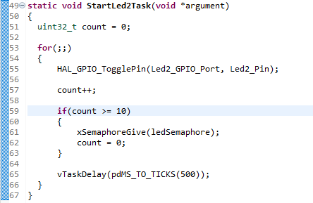
The actual implementation is shown in the following code example.
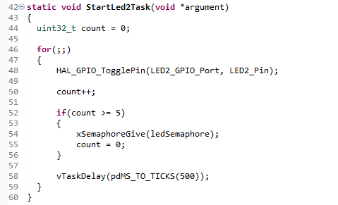
In the code above, the count variable is a local variable used only inside the LED2 Task. Each time LED2 blinks, the count value is increased by 1.
count++;When the count value reaches 5, the task calls xSemaphoreGive() to set the Binary Semaphore.
xSemaphoreGive(ledSemaphore);At this point, the LED1 Task, which has been waiting for the semaphore, can be released from the Blocked state.
After giving the semaphore, the count value is reset to 0 so that the same operation can be repeated.
count = 0;Therefore, the LED2 Task blinks LED2 every 500 ms and sends an event to the LED1 Task once every five blinks.
The important point here is that the LED2 Task does not directly call the LED1 Task. It only gives the semaphore. The FreeRTOS scheduler determines when the LED1 Task will actually run.
In other words, the two tasks are not directly connected. They are loosely connected through the Binary Semaphore. This is a basic method for implementing task-to-task event signaling in FreeRTOS.
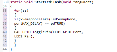
Implementing the LED1 Task (Semaphore Take)
In this section, we will implement the LED1 Task, which receives the semaphore event generated by the LED2 Task.
Unlike a periodically running task, the LED1 Task remains in the Blocked state until a semaphore becomes available. When the LED2 Task gives the semaphore, the LED1 Task is immediately unblocked and blinks LED1.
The operation flow of the LED1 Task is as follows:
Wait for Semaphore
        ↓
Receive Semaphore
        ↓
Blink LED1
        ↓
Wait for Semaphore
Rather than executing continuously, the LED1 Task remains idle until an event occurs. This allows the task to consume no CPU time while waiting, making the application more efficient.
The actual implementation is shown in the following code example.
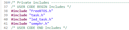
Why Is semphr.h Required?
For example, FreeRTOS organizes its features into separate header files as shown below:
| Feature | Header File |
|---|---|
| Task | task.h |
| Queue | queue.h |
| Semaphore | semphr.h |
| Event Group | event_groups.h |
Therefore, whenever you use semaphore-related APIs, you must include the following header file:
#include "semphr.h"After fixing the header file issue, the project built successfully. The code was then downloaded to the board for testing.
Although LED1 operated correctly, it was observed that LED1 toggled more frequently than expected.
After examining the behavior, it was found that LED1 changed state once for approximately every 2.5 blinks of LED2. This was not the intended result.
The desired behavior was for LED1 to change state only after LED2 had blinked five times. Therefore, the counting logic needed to be based on the actual number of LED blinks rather than the number of state changes.
A single LED blink consists of two state transitions:
LED ON
   ↓
LED OFF
In other words, one complete blink requires both an ON transition and an OFF transition.
Therefore:
1 Blink = 2 State Changes
5 Blinks = 10 State Changes
For this reason, the counter threshold was changed from 5 to 10.
After modifying the count condition to 10, LED2 completed five full blink cycles before giving the semaphore, and LED1 then changed state exactly once as intended.
This result also highlights an important debugging lesson: when using HAL_GPIO_TogglePin(), the counter tracks state changes, not complete blink cycles. Understanding this distinction helps prevent timing and counting errors in event-driven FreeRTOS applications.
Through this experiment, we verified that a Binary Semaphore can be used to deliver an event from one task to another.
Conclusion
In this practice, we explored how to use a Binary Semaphore in FreeRTOS to deliver events between tasks.
The LED2 Task was designed to give a semaphore after executing a specified number of times, while the LED1 Task waited for the semaphore and toggled its LED state when the semaphore was successfully taken.
During the experiment, we encountered compilation errors caused by a missing semaphore header file. We also observed unexpected behavior resulting from the difference between the number of LED state changes and the actual number of LED blink cycles. By resolving these issues step by step, we gained a clearer understanding of how semaphores work.
Most importantly, we confirmed that a semaphore does not transfer data. Instead, it serves as a signaling mechanism that informs another task that a specific event has occurred. We also observed that a task waiting for a semaphore enters the Blocked state and consumes no CPU time while waiting.
In the next practice, we will use a Queue to transfer actual data between tasks. Comparing Queue-based communication with semaphore-based signaling will provide a deeper understanding of task communication mechanisms in FreeRTOS.


“STM32C0316-DK FreeRTOS Practice #2 – Task-to-Task Event Signaling Using Semaphores”에 대한 1개의 생각