Overview
In the previous article, we manually ported FreeRTOS-Kernel V11.3.0 to the STM32C0316-DK development board and verified that a simple LED task was running correctly.
You can read the previous article here:
How to Manually Install FreeRTOS-Kernel V11.3.0 on STM32C0316-DK
This article is the second post in the series and the first practical FreeRTOS example. We will create two tasks that blink LEDs at different intervals and examine why multiple tasks appear to run simultaneously on a single-core MCU.
Through this experiment, we will learn the basic principles of FreeRTOS task scheduling.
Although the STM32C031 contains only a single CPU core and can execute only one task at a time, multiple tasks seem to run concurrently because the FreeRTOS scheduler rapidly switches execution between them. In this example, we will observe this behavior directly by blinking two LEDs at different rates.
To keep the series moving efficiently, rather than creating a new project from scratch, we will duplicate the previous project and continue our development from that baseline. This approach is also common in real-world embedded development, where existing projects are frequently extended with additional functionality.
As the examples become more complex, the amount of user code will naturally increase. To keep the project organized, we will create a separate folder named MyApp and place all application-specific code inside it. This separation makes it easier to distinguish between STM32CubeIDE-generated code, FreeRTOS kernel code, and user-written application code.
In this article, we will first create a new project by copying the previous one and then organize our application code using the MyApp folder structure.
Let’s begin by duplicating the previous project.
Project Setup
Copying the Project
As mentioned in the overview, starting from this experiment we will no longer create a new project from scratch for each example. Instead, we will duplicate the previous project and continue building on it. As the series progresses, both the project configuration and source code will gradually increase in size. Reusing an existing project is therefore much more efficient than repeatedly configuring everything from the beginning.
Simply copying a project, however, is not enough to make it work correctly. Several additional steps are required after the copy process. This provides a good opportunity to learn how to create a new experiment project by duplicating an existing one.
The following tasks will be performed after copying the project:
- Copy the project
- Rename the project
- Delete the Debug folder and the
Debug.launchfile - Rename the IOC file
- Modify the Refresh Policy
- Configure the Debug Configuration
When a project is copied and pasted in STM32CubeIDE, the IDE automatically creates a new project name with an incremented version number. For example, if the original project is named FreeRTOS_LED_V1, the copied project may be created as FreeRTOS_LED_V2.
Now let’s begin by copying the project.
Copying the Project
In the Project Explorer window, locate the existing project C9SW-FreeRTOS-Manual-v1.0. Right-click the project, select Copy, and then choose Paste within the same workspace. A dialog similar to the one shown below will appear.
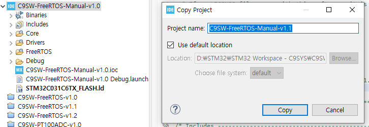
As shown in the dialog, STM32CubeIDE automatically increments the version number of the copied project. In this example, the project name is changed from C9SW-FreeRTOS-Manual-v1.0 to C9SW-FreeRTOS-Manual-v1.1.
This automatic versioning feature is convenient when creating multiple experiment projects based on a common template, as it helps keep each stage of development organized and easy to track.
Renaming the Project
You may keep the automatically generated project name from the previous step, or you can rename it to something more meaningful.
Since this project is the first practical example in the FreeRTOS tutorial series, we will use a feature-oriented naming convention to make it easier to distinguish projects as the series grows.
In this example, we will demonstrate multitasking using two LED tasks. Therefore, the project will be renamed to C9SW-FreeRTOS-M-LedTask.
By using descriptive project names, the purpose of each project can be identified immediately without relying on version numbers. For this reason, no additional version number will be included in the project name.
The new project name is therefore:
C9SW-FreeRTOS-M-LedTask
Here, M stands for Manual, indicating that FreeRTOS was manually ported into the project rather than added through the STM32CubeMX FreeRTOS middleware.
The figure below shows the newly created project after it has been renamed.
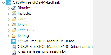
At this stage, the project name has been updated successfully. However, several files inside the project still retain the original name. In the following sections, we will update these files and project settings to ensure that the renamed project builds and debugs correctly.
Deleting the Debug Folder and Debug.launch File
After creating the new project, you will notice that a Debug folder is included in the project structure.
This folder contains build output files and other artifacts that were generated when the original project was compiled. Because these files are copied together with the project, it is a good practice to remove them and start with a clean project environment.
Deleting the Debug folder does not affect the source code. When the project is built again, STM32CubeIDE automatically recreates the folder and generates all required build files.
In addition, the original project’s debug launch configuration file, C9SW-FreeRTOS-Manual-v1.0 Debug.launch, is also copied into the new project. Since this file still references the previous project configuration, it should be deleted as well.
Therefore, delete both the Debug folder and the Debug.launch file before proceeding.
After removing these files, we will rebuild the project and generate a fresh set of build and debug configuration files for the new project.
Renaming the IOC File
Although the project itself has been renamed, the IOC file still retains the name of the original project. While this does not prevent the project from functioning correctly, having different names for the project and its IOC file can lead to confusion when managing multiple projects.
To keep the project organized and maintain consistency, we will rename the IOC file to match the current project name.
Original file:
C9SW-FreeRTOS-Manual-v1.0.iocRenamed file:
C9SW-FreeRTOS-M-LedTask.iocThe figure below shows the project after the IOC file has been renamed.
Keeping the project name and IOC file name synchronized makes the project structure easier to understand and helps avoid mistakes when working with multiple STM32CubeIDE projects.
After renaming the IOC file, refresh the project in STM32CubeIDE or reopen the project to verify that the new IOC file is recognized correctly.
Modifying the Refresh Policy
After renaming both the project and the IOC file, it is a good idea to review the Refresh Policy settings as well.
When a project is copied, some project-specific settings may still reference the original project. In most cases, this does not cause any immediate problems, but updating these settings helps keep the project configuration clean and consistent.
For this reason, we will verify that the Refresh Policy matches the current project name.
In STM32CubeIDE, select the project and navigate to:
Properties → C/C++ Build → Refresh Policy
When a project is renamed properly, STM32CubeIDE often updates the Refresh Policy automatically. However, if the project has not been refreshed or if the rename process was incomplete, the Refresh Policy may still contain references to the previous project.
Therefore, it is worth checking this setting. If an entry referencing the old project name is found, remove it and add a new entry that points to the current project.
The Refresh Policy determines which resources STM32CubeIDE refreshes automatically after build operations. Keeping this configuration aligned with the current project helps prevent issues where newly generated files are not immediately recognized by the IDE.
A typical Refresh Policy configuration is shown in the figure below.
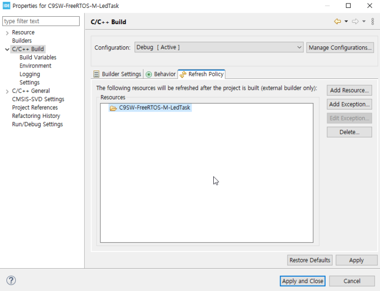
After modifying the settings, click Apply and Close to save the changes.
This step ensures that STM32CubeIDE can correctly recognize and manage the project files even after the project has been renamed.
With the project cleanup now complete, the next step is to perform a Build operation. This will regenerate the Debug folder and allow us to verify that the project builds successfully and functions as expected.
Building the Project and Verifying the Debug Configuration
So far, we have completed several project maintenance tasks, including renaming the project, cleaning up the Debug folder, renaming the IOC file, and updating the Refresh Policy settings.
The first step is to perform a Build operation and verify that the project compiles successfully.
Since this project was created by copying a previously working project, the build should complete without errors unless an issue was introduced during the renaming or cleanup process.
If the build finishes successfully, the next step is to verify the Debug Configuration settings.
From the STM32CubeIDE menu, select:
Debug As → Debug Configurations…
The following dialog will appear.
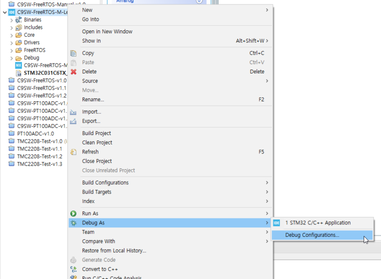
When you click Debug Configurations…, a window similar to the one shown below will appear.
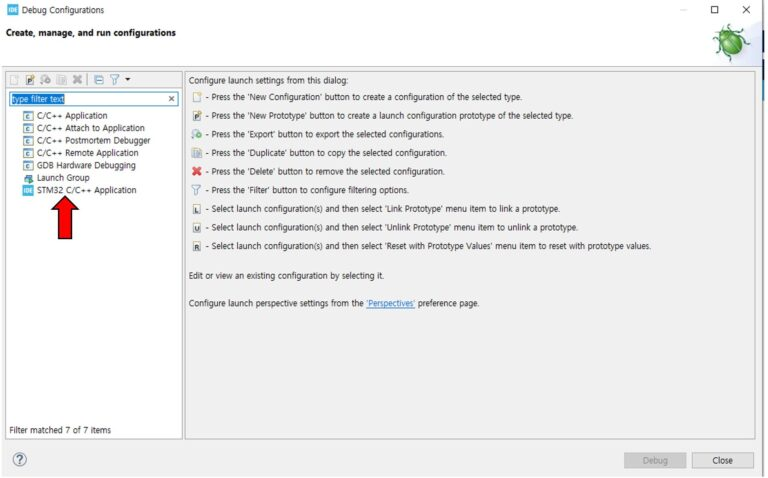
In the left-hand panel, select:
STM32 C/C++ Application
a window similar to the one shown below will appear.
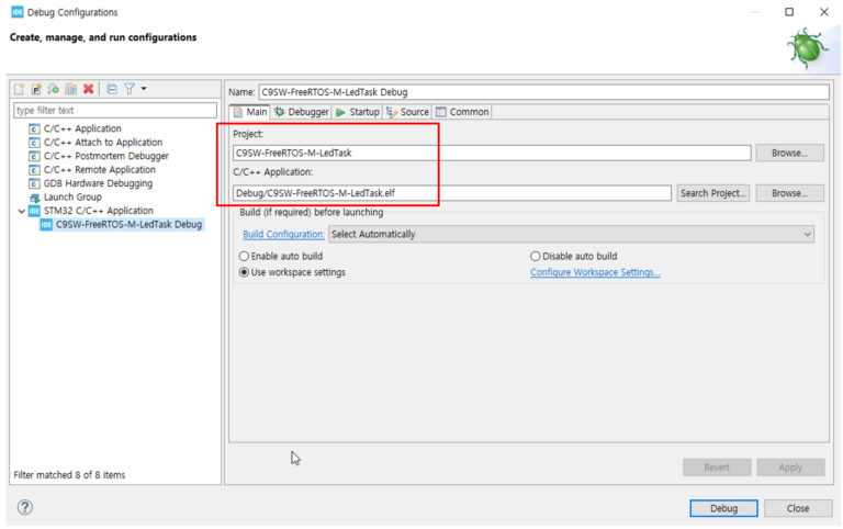
Check the items highlighted in the red box.
- Project:
C9SW-FreeRTOS-M-LedTask - C/C++ Application:
Debug/C9SW-FreeRTOS-M-LedTask.elf
Verify that both entries match the current project name.
If the name of the previous project is still displayed, select the correct project again or create a new debug configuration for the current project.
Once you have confirmed that the settings are correct, click the Debug button in the lower-right corner of the window.
STM32CubeIDE will download the program to the STM32C0316-DK board and start a debug session. As in the previous experiment, you should see the LED blinking normally.
Successful execution confirms that the project copy process and environment configuration have been completed correctly.
Creating a MyApp Folder for User Application Code
As development progresses, the size of the application will naturally increase. In the early stages, it may be sufficient to place a few functions directly in main.c, but as more features are added, the source code can quickly become difficult to organize and maintain.
To keep the project structure clean and manageable, we will create a separate folder named MyApp for user application code. All application-specific code developed in future experiments will be placed in this folder.
The folder does not have to be named MyApp. The important point is to separate user-written code from code generated by STM32CubeIDE. For consistency throughout this tutorial series, we will use the name MyApp.
As shown below, create a new folder named MyApp under the project directory.
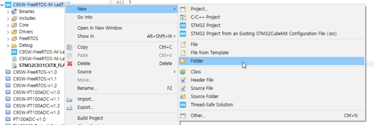
Using the same procedure, create two additional folders inside MyApp:
- inc – for header files (
.h) - src – for source files (
.c)
The completed folder structure should look similar to the figure below.
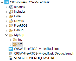
From this point forward, all user application code will be managed inside the MyApp folder. A common convention is to place header files in the inc folder and source files in the src folder.
Although STM32CubeIDE already provides folders such as Core, keeping user code in a dedicated location makes the project easier to maintain as it grows. This approach also helps clearly distinguish between generated code, FreeRTOS kernel code, and application-specific code.
Finally, add MyApp/inc to the project’s Include Path and add MyApp/src to the Source Location settings so that STM32CubeIDE can compile the user application code correctly.
Once these settings have been completed, the project structure is ready for future FreeRTOS experiments and application development.
LED Hardware Configuration
For this experiment, the LEDs must be physically connected to the board, and the program must know which GPIO pins are assigned to them.
We will use two LEDs. One is the LED already mounted on the board, and the other is an external LED connected with a simple circuit.
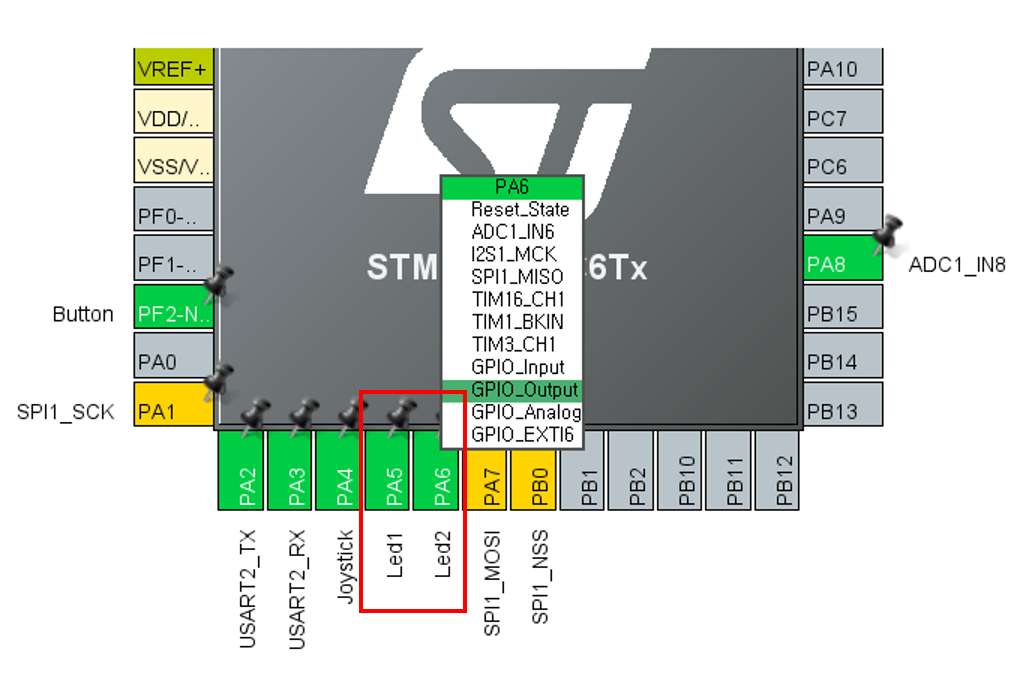
The on-board LED is connected to PA5, and we will define it as Led1. The external LED is connected to PA6, and we will define it as Led2.
The figure below shows the CubeMX configuration for Led1 and Led2.
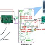
The external Led2 circuit was built on a breadboard and connected to the 20-pin CN1 connector as shown below.
Led2 connection:
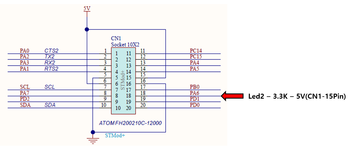
With the hardware configuration for both LEDs complete, the test environment is now ready.
In the next section, we will create the LED tasks and verify whether two tasks appear to run at the same time under FreeRTOS.
Writing the LED Tasks
So far, we have configured the project environment, created the MyApp folder for managing user code, and completed the LED hardware setup.
Now we will write the LED tasks that actually blink the LEDs.
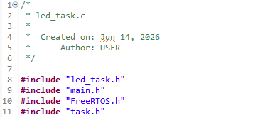
In the src folder under MyApp, create a file named led_task.c.
In the inc folder, create a file named led_task.h.
From now on, all code related to the LED tasks will be managed in these two files.
Creating the LED Task Header File
In the header file, we define the task initialization function, LedTask_Init().
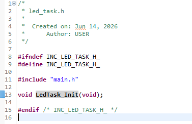
The LedTask_Init() function will create two LED tasks using FreeRTOS xTaskCreate().
Creating the LED Task Source File
First, include the led_task.h header file, along with main.h, FreeRTOS.h, and task.h.
Next, declare StartLed1Task() and StartLed2Task(). These functions are the entry functions of the tasks created by FreeRTOS, and they will actually control the LEDs.
![]()
These two functions are declared as static because they are used only inside led_task.c. This prevents them from being accessed from other source files and keeps the LED task module internally organized.
In contrast, LedTask_Init() must be called from main.c, so it is declared in the header file and is not defined as static.
The following code implements LedTask_Init().
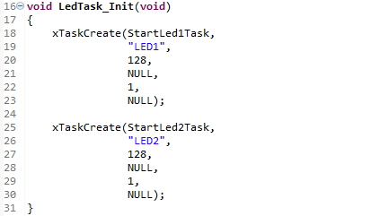
The first argument is the task entry function, the second argument is the task name, the third argument is the task stack size, and the fifth argument is the task priority.
Next, we implement the two tasks that blink the LEDs.
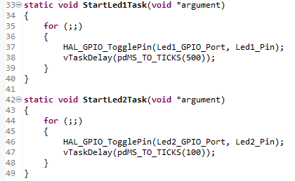
Both tasks are assigned the same priority. Therefore, when both tasks are in the Ready state, the FreeRTOS scheduler can allocate CPU time to them alternately.
StartLed1Task() toggles LED1 inside an infinite loop and then waits for 500 ms using vTaskDelay(pdMS_TO_TICKS(500)).
StartLed2Task() has the same structure, but its delay time is set to 100 ms. As a result, LED2 blinks faster than LED1.
Although the two tasks operate at different intervals, they are created and executed together under FreeRTOS. By observing the LEDs blinking independently, we can confirm the basic multitasking behavior of FreeRTOS.
Why Do Two Tasks Appear to Run Simultaneously?
The STM32C031 is a single-core MCU. However, as we observed in the experiment, two tasks appear to run at the same time.
If only one task can actually execute at any given moment, why does it look like multiple tasks are running simultaneously?
To answer this question, we need to understand how the FreeRTOS scheduler works.
The diagram below illustrates task execution from the user’s perspective. Even though the CPU has only one core, all tasks appear to be running continuously and concurrently.
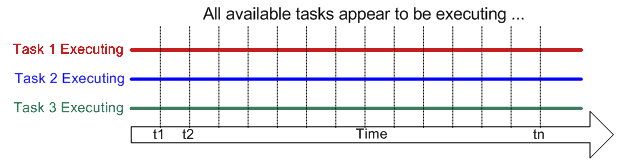
From the user’s point of view, each task seems to execute independently without interruption.
In reality, however, only one task is executing at any given moment. The FreeRTOS scheduler repeatedly switches between tasks at very short time intervals through a mechanism known as context switching. Because these switches occur so quickly, multiple tasks appear to run simultaneously.
The next diagram shows what is actually happening inside the CPU.
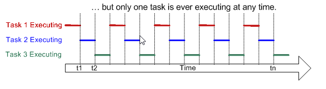
As shown in the figure, the CPU executes only one task at a time. The processor runs Task 1 for a short period, then switches to Task 2, then to Task 3, and continues this cycle repeatedly.
The scheduler saves the execution context of the currently running task and restores the context of the next task before resuming execution. This process is called context switching.
Because context switching occurs extremely rapidly, users perceive the tasks as running concurrently. This behavior is known as multitasking, and it is one of the core features provided by FreeRTOS.
On a single-core MCU, multitasking does not mean that multiple tasks execute at exactly the same instant. Instead, it means that the scheduler shares CPU time among multiple tasks so efficiently that they appear to run in parallel.
This concept forms the foundation of most real-time operating systems and allows embedded applications to manage multiple independent activities while using only a single processor core.
For more detailed information, refer to the FreeRTOS documentation:
Conclusion
In this article, we used FreeRTOS on the STM32C0316-DK development board to create and run two independent LED tasks.
We first learned how to create a new experiment project by copying an existing project. We also organized the application structure by creating a dedicated MyApp folder for user code management.
Next, we implemented two LED tasks with different execution periods. LED1 was configured to toggle every 500 ms, while LED2 toggled every 100 ms.
Although the STM32C031 contains only a single CPU core, the two LEDs appeared to operate independently. This demonstrated how multiple tasks can appear to run simultaneously under FreeRTOS.
In reality, the CPU executes only one task at a time. The FreeRTOS scheduler rapidly switches between tasks through context switching, creating the illusion of concurrent execution.
Through this experiment, we explored one of the most fundamental concepts of FreeRTOS: multitasking on a single-core MCU.
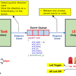
In the next article, we will demonstrate how one task can trigger another task using a Semaphore when a predefined condition is met.
STM32C0316-DK FreeRTOS Practice #2 – Task-to-Task Event Signaling Using Semaphores


“STM32C0316-DK FreeRTOS Tutorial #1 – Why Two Tasks Seem to Run at the Same Time”에 대한 2개의 생각