Overview
So far, we have learned how to manually install FreeRTOS, explored the concept of multitasking using two LED Tasks, and practiced Task-to-Task event delivery using a Semaphore.
In this tutorial, we will learn how to use a FreeRTOS Queue on the STM32C0316-DK to transfer data between Tasks.
If a Semaphore is used to signal whether an event has occurred, the biggest difference with a Queue is that it can transfer actual data along with the event.
In this example, we will use the built-in ADC joystick on the STM32C0316-DK board. This joystick outputs different ADC values depending on its direction, and the Button Task reads these values and converts them into button events such as LEFT, RIGHT, UP, and DOWN.
These generated button events are then delivered to the LED Task through a Queue, and the LED Task controls the corresponding LED based on the received event.
Through this example, you will naturally understand the Producer–Consumer architecture and the method of transferring data between Tasks using a Queue.
For more information about FreeRTOS Queues, please refer to the official FreeRTOS website.
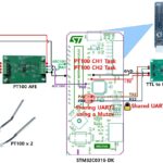
Hardware Configuration
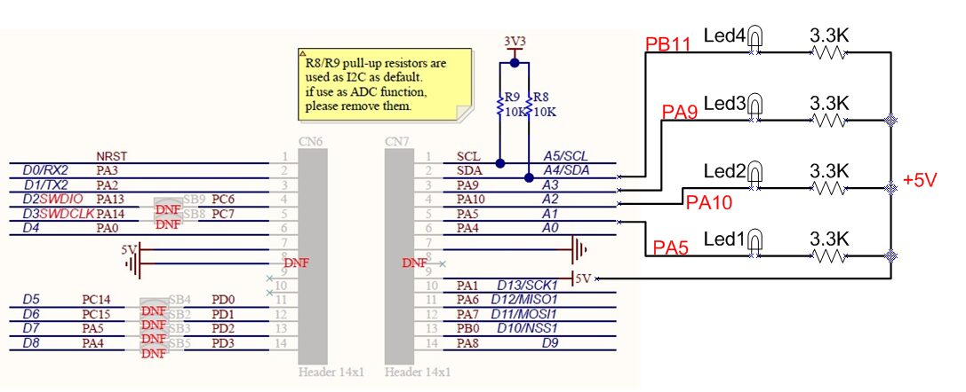
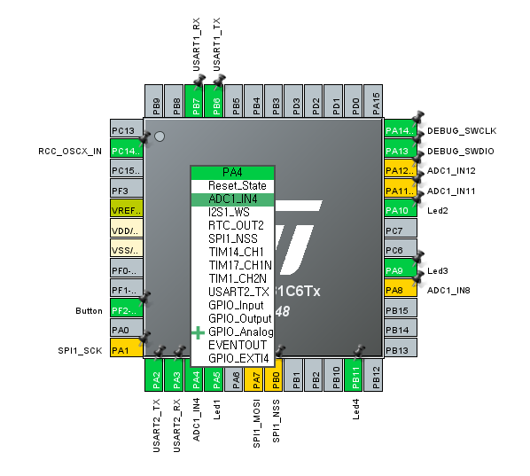
For this FreeRTOS Queue tutorial, we will configure the hardware as shown in the figure below.
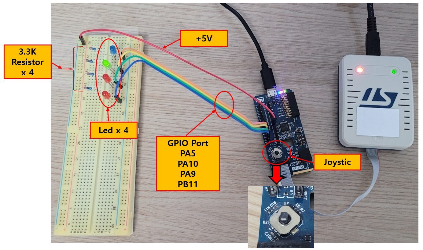
The four LEDs are connected to the header pins of the 28-pin DIP socket on the development board, and the actual circuit is shown below.
The STM32C0316-DK board includes a built-in ADC joystick that supports directional input. When the LEFT, RIGHT, UP, or DOWN button is pressed, it outputs a different ADC value. In this tutorial, these ADC values are used to generate button events.
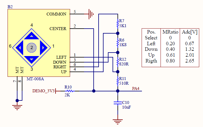
The circuit for the joystick is shown below.
Since each direction of the joystick outputs a different ADC value, the Button Task can determine which button has been pressed by reading the ADC value. The detected result is then transferred to the LED Task through a Queue.
In addition, four LEDs have been added to the breadboard to verify that the button events transferred through the Queue are processed correctly.
Each LED is connected to a GPIO output and is turned on or off according to the button event received through the Queue.
The GPIOs used in this tutorial are as follows.
| Function | GPIO |
|---|---|
| ADC Joystick | PA4 |
| LED1 | PA5 |
| LED2 | PA10 |
| LED3 | PA9 |
| LED4 | PB11 |
Operation Overview
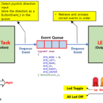
In this example, the Joystick Task and the LED Task communicate with each other through a Queue to exchange data. The diagram below illustrates this overall structure.
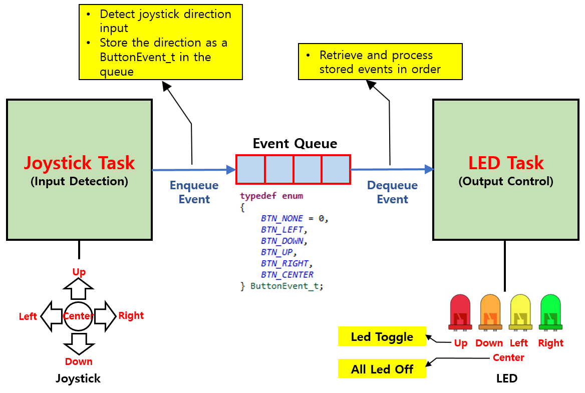
The Joystick Task reads the joystick direction at regular intervals. The detected direction is not treated as a simple ADC value but is converted into a ButtonEvent_t event (BTN_UP, BTN_DOWN, BTN_LEFT, BTN_RIGHT, BTN_CENTER).
The generated event is stored in the Queue using xQueueSend(). Since the Queue follows a FIFO (First In, First Out) structure, the event that is stored first is also processed first.
The LED Task waits for an event to arrive in the Queue by calling xQueueReceive(). When a new event is received, it retrieves the event, determines which button was pressed, and controls the corresponding LED.
In this example, the behavior is as follows.
- UP : Toggle the corresponding LED
- DOWN : Toggle the corresponding LED
- LEFT : Toggle the corresponding LED
- RIGHT : Toggle the corresponding LED
- CENTER : Turn off all LEDs
As shown above, the two Tasks do not call each other’s functions directly. Instead, they communicate only through the Queue, which completely separates input processing from output processing. This is one of the biggest advantages of using FreeRTOS Tasks. Even when new functionality is added, each Task can be modified independently.
The key point of this example is not controlling the LEDs themselves, but understanding how a Queue allows events generated by one Task to be processed in order by another Task.
ADC and GPIO Configuration
On the STM32C0316-DK, each joystick button is not connected to a separate GPIO pin. Instead, the joystick uses a resistor divider network and is read as an analog input.
Therefore, to read the joystick, you must use the ADC rather than GPIO input.
As shown in the joystick circuit above, the resistor network generates a different voltage for each button, and these voltages are applied to PA4.
Each directional button produces a different voltage level, and the ADC converts this voltage into a digital value.
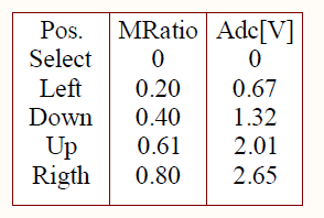
The Select button outputs 0 V as the Center button, while Left outputs 0.67 V, Down outputs 1.32 V, Up outputs 2.01 V, and Right outputs 2.65 V.
To verify which button has been pressed, this example uses four LEDs. Therefore, the corresponding GPIO pins must be configured as GPIO Output.
The GPIO pins used are as follows.
PA5 LED1
PA4 ADC Joystick
PA10 LED2
PA9 LED3
PB11 LED4
Now let’s configure the STM32 peripherals required for the joystick and LEDs.
In this example, STM32CubeMX is used to configure the ADC and GPIO. The joystick direction is detected using the ADC input on PA4, and the LEDs are controlled through four GPIO output pins.
First, configure the ADC, and then configure the GPIO pins used for the LED outputs.
The figure below shows the configuration screen with PA4 set to ADC1_IN4.
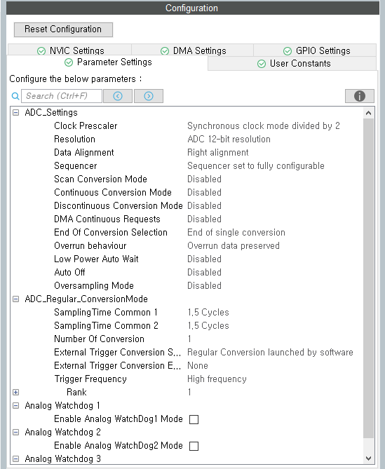
The Parameter Settings are configured as shown below. In this example, the default settings provided by STM32CubeMX are used without any modifications.
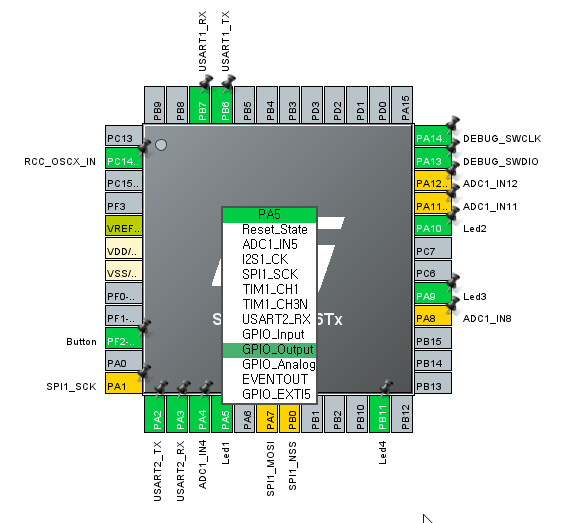
Configure PA5, PA10, PA9, and PB11 as Output pins to control the LEDs.
Set all GPIO pins to Output Push-Pull mode, and leave the remaining options at their default values.
Once the configuration is complete, run Generate Code to generate the project.
The generated initialization code is automatically called from main(), so there is no need to write separate initialization code.
The ADC operating principle and each configuration item will be covered in a separate article. In this example, only the minimum settings required for the Queue tutorial are used.
Creating the Joystick Task
Now let’s create the Joystick Task, which reads the joystick input and sends events to the Queue.
The Joystick Task is responsible for periodically checking which direction the user has moved the joystick. The joystick direction is determined using the analog value read by the ADC. Instead of using the raw ADC value directly, it is converted into a ButtonEvent_t event that can be used by the application.
By converting the ADC value read from the hardware into an abstract event, other Tasks do not need to know anything about the ADC operation or the actual voltage values. They simply receive and process the event. As a result, the input processing and output processing are clearly separated, making the overall program structure much simpler.
Creating the joystick.c and joystick.h files
First, create the joystick.c and joystick.h files.
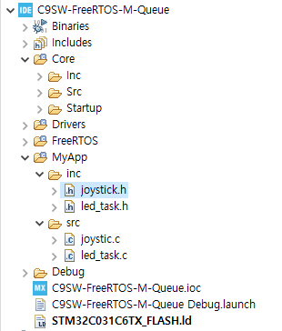
Copy the previous project, C9SW-FreeRTOS-M-Semaphore, and create a new project named C9SW-FreeRTOS-M-Queue.
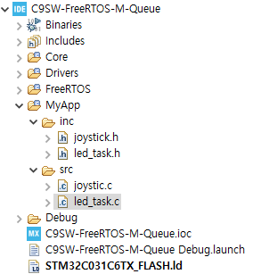
Create joystick.c in MyApp > src, and create joystick.h in the MyApp > inc folder.
The result should look like the screen below.
Implementing the joystick.c and joystick.h Code
The code for joystick.h is as follows.
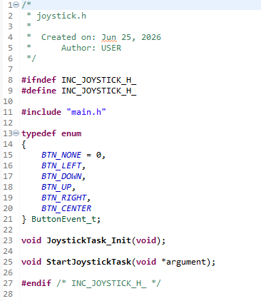
The joystick.h file declares the ButtonEvent_t enumeration, which defines the events generated by the joystick, and the function prototypes used by the Joystick Task.
ButtonEvent_t defines events that represent each joystick direction. Instead of passing the ADC value directly, it converts the input into meaningful events such as BTN_LEFT and BTN_RIGHT before sending them to another Task.
In addition, JoystickTask_Init() is used to initialize the joystick, while StartJoystickTask() is the entry function of the Joystick Task executed by FreeRTOS. The actual joystick input is read and converted into events within this Task function.
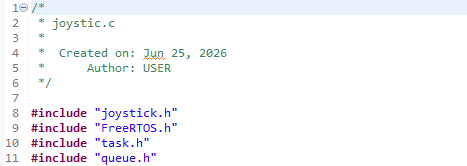
In joystick.c, include the following header files to use the FreeRTOS Queue API and the ADC.
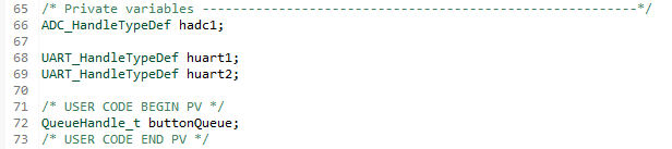
To read the joystick direction, an ADC_HandleTypeDef is required to control the ADC. In addition, a QueueHandle_t is required to send the generated events to the Queue.
These two handles are declared as global variables in main.c, so they are referenced in joystick.c using the extern keyword.
The following are hadc1 and buttonQueue declared in main.c.
In joystick.c, declare them with the extern keyword as shown below so that the handles created in main.c can be used.
![]()
The extern keyword declares a global variable defined in another source file so that it can also be used in the current file. Therefore, instead of creating new variables, joystick.c shares and uses the same hadc1 and buttonQueue instances created in main.c.
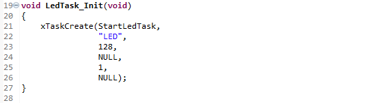
Next, let’s create the Joystick Task. In the JoystickTask_Init() function, call xTaskCreate() to create the StartJoystickTask() task.
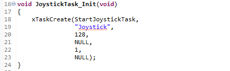
Each argument of xTaskCreate() has the following meaning.
- StartJoystickTask : The function that will be executed when the Task starts.
- “Joystick” : The name of the Task displayed during debugging.
- 128 : The stack size allocated to the Task.
- NULL : The parameter passed to the Task. It is not used in this example.
- 1 : The priority of the Task.
- NULL : Since the created Task handle is not stored,
NULLis used.
This function does not actually run the Task immediately. Instead, it creates the Joystick Task and registers it with the FreeRTOS Scheduler. When the Scheduler starts, StartJoystickTask() runs as an independent Task.
Next, we will implement the StartJoystickTask() function registered with the FreeRTOS Scheduler. This function reads the ADC value of the joystick, converts it into a ButtonEvent_t event, and sends it to the Queue.
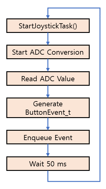
The Joystick Task repeatedly performs the following operations inside an infinite loop.
- Start ADC conversion
- Read the ADC value
- Convert the ADC value into a
ButtonEvent_tevent - Store the event in the Queue
- Wait for a certain period of time
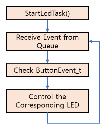
The following shows the overall operation flow.
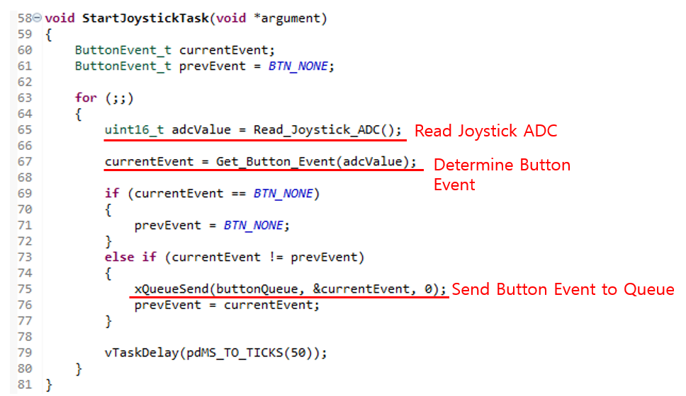
The implemented code is shown below.
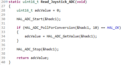
Reading the ADC Value
The first operation performed inside the infinite loop is reading the joystick’s ADC value.
![]()
The Read_Joystick_ADC() function converts the analog voltage applied to PA4 into a digital value using the ADC and returns the result. Since each joystick direction produces a different ADC value, this value is used in the next step to determine which button has been pressed.
The implementation of the Read_Joystick_ADC() function is shown below.
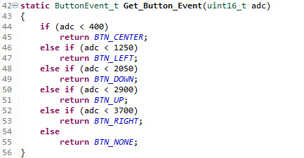
Creating a ButtonEvent_t
After reading the ADC value, the next step is to determine the button direction and generate a ButtonEvent_t event.
![]()
The Get_Button_Event() function compares the ADC value with predefined voltage ranges and returns one of the following events: BTN_LEFT, BTN_RIGHT, BTN_UP, BTN_DOWN, or BTN_CENTER.
The implementation of the Get_Button_Event() function is shown below.
Preventing Repeated Button Inputs
If the joystick is held in the same direction, the same ADC value is read repeatedly. If every value is stored in the Queue, the same event will be sent continuously, causing the corresponding LED to operate repeatedly.
To prevent this, the previous event (prevEvent) is compared with the current event (currentEvent).
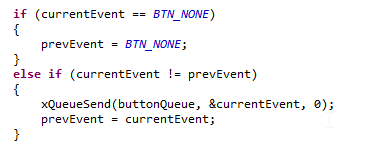
If no button is pressed, prevEvent is reset to BTN_NONE. The program proceeds to the next step only when the previous event and the current event are different.
In other words, an event is generated only when a button is pressed for the first time, and no additional events are generated while the same button continues to be held down.
Storing Events in the Queue
Whenever a new button event is generated, it is sent to the LED Task through the Queue.
![]()
buttonQueue is a Queue that stores ButtonEvent_t events, and currentEvent is added to the end of the Queue.
In this example, the block time is set to 0, so if the Queue is full, the function returns immediately without waiting. For a typical button input application, the Queue is very unlikely to become full, so this approach is sufficient.
Repeating at Regular Intervals
Finally, the Task waits for a fixed period before reading the joystick again.
![]()
After waiting for 50 ms, the ADC is read again, so the joystick input is checked at a rate of approximately 20 Hz. This update rate is more than sufficient for processing button inputs while also preventing unnecessary CPU usage.
Conclusion
StartJoystickTask() is responsible for handling joystick input. It reads the ADC value, generates a button event, and stores it in the Queue. In addition, it compares the current button state with the previous one to prevent the same event from being stored in the Queue repeatedly.
By converting the input into events and sending them through a Queue, the LED Task can process the events without needing to know any details about the input device. This separation of input and output is a common design pattern when developing applications with FreeRTOS Tasks.
Creating the LED Task
Now let’s create the LED Task, which reads the button events stored in the Queue and controls the LEDs.
In the previous section, the Joystick Task read the joystick direction, generated ButtonEvent_t events, and stored them in the Queue. However, the events stored in the Queue do nothing until another Task retrieves and processes them.
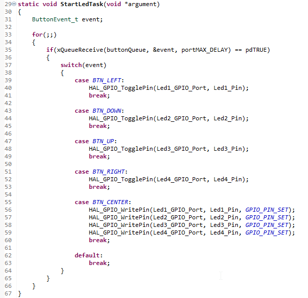
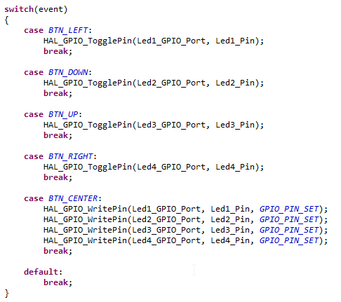
In this section, we will implement the LED Task, which uses xQueueReceive() to read the events from the Queue in the order they were stored and controls the corresponding LED based on the event type.
The LED Task waits for new events to arrive in the Queue. When an event is received, it controls the corresponding LED according to the button that was pressed. In other words, the Joystick Task is responsible for generating events, while the LED Task is responsible for processing those events.
By separating the Task that handles input from the Task that handles output, each Task has a single responsibility, making the program structure simpler and easier to maintain. In addition, because the two Tasks communicate only through the Queue, they remain independent and do not directly depend on each other.
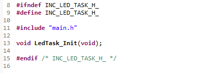
First, create the led_task.c and led_task.h files, and then implement the LED Task.
Conclusion
In this tutorial, we implemented communication between two Tasks using a FreeRTOS Queue.
The Joystick Task reads the joystick direction, generates a ButtonEvent_t event, and stores it in the Queue. The LED Task receives the event from the Queue and controls the corresponding LED.
By using a Queue, two Tasks can exchange data safely without calling each other’s functions directly. In addition, separating the input-processing Task from the output-processing Task makes the program structure simpler and easier to maintain.
Although this example demonstrates a simple joystick event transfer, Queues can be used to transfer many types of data between Tasks, including sensor data, UART receive data, and measurement results. For this reason, the Queue is one of the most commonly used Task-to-Task communication mechanisms in FreeRTOS.
Below are links to the previous articles in this FreeRTOS series
How to Manually Install FreeRTOS-Kernel V11.3.0 on STM32C0316-DK
STM32C0316-DK FreeRTOS Tutorial #1 – Why Two Tasks Seem to Run at the Same Time